-
The MB/GPW Spare Parts Kit, Tools
Kit,
Standard Issue Equipment &
Accessories,
Special Issue Equipment &
Accessories Page

Please don't pirate my pictures or text. Ask
my permission.
Copyright
© 1998-2012 Brian French. All Rights Reserved
Spare Parts Kit
| Item Nomenclature |
Fed # /
MFG. # |
Willys # |
Ford # |
Storage Location |
| Bag, Spare Parts |
8-B-11 |
A-7686 |
GPW-17008 |
Glove Box *1 |
| Belt, Fan |
33-B-76 / Gates
79T |
A-1495/A-9490 |
GPW-8620 |
Bag, Spare Parts |
| Caps, Tire Valve, boxed, (5x #GPW-1720) |
8-C-650 |
A-7681 |
GPW-18322 |
Bag, Spare Parts |
| Cores, Tire Valve, boxed, (5x #B-1725) |
8-C-6750 |
A-7682 |
GPW-18320 |
Bag, Spare Parts |
| Lamp, Incandescent, 6-8v, 3cp |
17-L-5215 / Mazda
63 |
A-8385 |
B-13166 |
Bag, Spare Parts |
| Lamp-Unit, BO Stop, 6-8v, 3cp |
8-L-421 |
A-1078 |
GP-13485A |
Bag, Spare Parts |
| Lamp-Unit, BO Tail, 6-8v, 3cp |
8-L-415 |
A-1075 |
GP-13491A |
Bag, Spare Parts |
| Lamp-Unit, Service Tail & Stop, 6-8v, 3-21cp |
8-L-419 |
A-1074 |
GP-13494A |
Bag, Spare Parts |
| Pins, Cotter, (Kit) |
42-P-5347 |
A-7683 |
GPW-18318 |
Bag, Spare Parts |
| Plug, Spark |
17-P-5365 /
Champion-J9 Autolite-AN7 AC-44 Firestone-17-P-5365
G503-03-40680 |
A-538 |
GPW-12405 |
Bag, Spare Parts |
| Tape, Friction (Roll) |
17-T-805 |
A-7684 |
GPW-17058 |
Bag, Spare Parts |
| Wire, Iron, 1/4 lb. Spool |
22-W-650 |
A-7685 |
GPW-17060 |
Bag, Spare Parts |
| *Bag, Key (with two H-700 keys) |
|
|
GPW-17082 |
Glove Box *2 |
| *Cap, Drain, Sump, Gas Tank Well |
|
A-3055 |
GPW-1111322 |
Glove Box *3 |
| *Plug, Drain, Floor, Body |
|
A-5120 |
358019-S 1/4" plug |
Glove Box *2 |
*1 ~ Right Rear Tool Box on Slatgrill MB models.
*2 ~ Not a spare part, but stored with
spare parts when not in use.
*3 ~ Not a spare part, but stored with
spare parts when not in use. Normally front cap was installed on sump,
while the rear cap was stored in glove box. The rear cap was installed
on sump only when fording water.
Bag, Spare Parts - A small bag sewn from light OD green cotton
cloth. Closed at the top by a drawstring. Stored in glove box on most jeeps
or in rear tool storage box on the early slatgrill MB's without a glove
compartment..
Belt, Fan - A coiled Fan Belt found marked in 3 versions.
-
Federal Ordnance Stock #,
-
Willys were marked in orange rubber ink "WILLYS A-9490 B.F. GOODRICH"
-
Ford's were marked in raised lettering "FORD GPW-8620"
Cap, Tire Valve - Extra Tire Valve Stem Cores & Caps were included.
Core, Tire Valve - Extra Tire Valve Stem Cores & Caps were
included.
Lamp, Incandescent - Small 6v bulb that fits both the Dash (Instrument)
Lamps and the Blackout Marker Lights.
Lamp-Unit, BO Stop ~ Lamp-Unit, BO Tail ~ Lamp-Unit, Service Tail
and Stop - B/O taillight assemblies consisting of metal housing, bulb,
and lens in one unit.
Pin, Cotter - a small cardboard box of many various size cotter
pins was included. Found marked in 3 versions.
-
in cardboard box marked with "Federal Ordnance Stock #42-P-5347 US
ARMY"
-
Willys have been found in a small metal canister with lid
-
Ford's were in cardboard box marked with "FORD GPW-18318"
Plug, Spark - Spark Plug with Gasket. Also found in several brand
versions.
Tape, Friction - A roll of black friction tape (early form of
electrical tape) that is 4 1/4" in diameter x 3/4" wide.
Wire, Iron, ¼ lb. Spool - a coil of easily bent iron
bailing wire described as "iron, annealed wire, 22ga. x 1/4 lb.
spool coil".
*Bag, Key (H-700 key) - a small cotton bag was included with
shipped jeeps. The bag was stored in the Glove Compartment. The bag contained
two H-700 keys which were used on the following;
-
Tool Box Locks (2)
-
Spare Tire Lock
-
Ignition Switches (early Keyed type)
-
Glove Box Lock (early Keyed type)
-
Black Out Light Switch on MBT Trailer (shown in manuals using base of key,
not key shaft). 1/4ton Bantam and Willys trailers (MBT / T-3) used the
same black out lights as jeeps did, however, switching between normal and
blackout lights on the jeep pulling the trailer did not affect the
status of the lights that were running on the trailer. The trailer
had its own light switch mounted to the front passenger side box frame.
Here is a photo
showing the small WWII MBT Jeep Trailer B/O Light Switch mounted in the
front of the lower passenger side. There was a small disc (door) that
swiveled out of the way to reveal a small set screw that can be turned
using the butt end of the Jeep H-700 Key to switch between running lights
and B/O lites.
*Cap, Drain, Sump, Gas Tank Well - Although not a spare part, it
was intended to be stored with the items in the Spare Parts Kit on the
jeep in the glove compartment. The jeep's gas tank sump (the well in the
body that the gas tank sat in) had a front & rear drain assembly.
Both drains consisted a neck (similar to a radiator neck #A-3056, #GPW-1111323)
held on by 3 rivets each, and a removable Cap (similar to a radiator cap).
The front cap was supposed to be installed at all times to keep out debris
kicked up by the front tires, except when flushing out the well. The rear
cap was supposed to be removed and stored in the glove box, except when
crossing streams or other water fording. After fording the rear cap would
be removed allowing the sump to drain. See TM 9-803, pg. 36, item #24.
*Plug, Drain, Floor, Body - Although not a spare part, it was
intended to be stored with the items in the Spare Parts Kit on the jeep
in the glove compartment. The jeep's front floor pan (the area of the body
that the occupants feet sat in) had a drain assemblies. One on the driver's
and one on the passenger's side. Both consisted of a pressed in fitting
(similar to a round captive nut) and a removable Plug (think pipe plug).
The plugs were supposed to be installed in dry periods, and be removed
and stored in the glove box during wet periods, such as rains, washings
or when crossing streams or other water fording. 1942 GPW Parts Manual
TM-10-1348 lists them as 1/4" Plug #358019-S, with a plain raw steel finish.
TM-10-1513 lists them as being brass.
Tools Kit
| Item Nomenclature |
Fed #
/ MFG. # |
Willys # |
Ford # |
Storage Location |
| Adapter, Grease Gun (Early, Short) |
|
A-6151 |
GPW-17126 |
Bag, Tool |
| Adapter, Grease Gun, (Mid-Late, Long 2-piece) |
41-A-14-800 - Alemite #6344
- Ord.#A-349744 |
A-11765 |
GPW-17126 (a) |
Bag, Tool |
| Adapter, Grease Gun, (Late, Long 1-piece) |
41-A-14-825 - Alemite #6517 |
|
GPW-17126-B |
Bag, Tool |
| Bag, Tool |
41-B-15 |
A-372 |
GPW-17005 |
Right Rear Tool Box |
| Chains, Snow, Type D, 6.00 x 16 (Qty 4) |
8-C-2538 |
A-1133 |
GPW-18136 |
4 Chains in 2 Chain Bags, Right Rear Tool Box |
| Crank, Hand, Engine Starting |
8-C-8322 |
A-289 |
GPW-17036 |
Hangs from clamp on inside of Rear Body Panel |
| Extinguisher, Fire, (1 Qt. Sprayer) |
58-E-202 |
A-616 |
GPW-17100A |
Inside Cowl, Bracket on Driver's side *4 |
| Gauge, Tire Pressure (gage) |
8-G-615 - Schrader
7188B |
A-6855 |
GPW-18325 |
Bag, Tool *5 |
| Gun, Grease, Push Type*, 9oz (Early) ~ pre 4/1944 |
41-G-1344-40 - Alemite
#5585 |
A-213 |
GP-17125 |
Left Rear Tool Box |
| Gun, Grease, Lever Type*, 16oz (Late) ~ post 3/1944 |
41-G-1330-60 Lincoln
#1078, ARO #2040
Alemite #6593 (body), Alemite #6594
(ass'y) |
|
G8T-17125 |
Engine Compartment, under hood in bracket on Driver's side |
| Hammer, Machinist's 16oz Ball Peen |
41-H-523 |
A-373 |
GP-17042 |
Bag, Tool |
| Jack, Screw type, 1 1/2 ton* |
41-J-66 #200-W-G |
A-1240 |
GPW-17080 |
Left Rear Tool Box |
| Oil Can, Straight Spout, 1/2 pint push bottom |
13-O-1530 |
A-379 |
GP-17038 |
Engine Compartment, Driver's Firewall in Bracket |
| Pliers, Combination, Slip Joint, 6 inch, Wire Cutting |
41-P-1650 |
A-374 |
GP-17028 |
Bag, Tool |
| Puller, Wheel Hub (flange) |
41-P-2962-700 |
A-1339 |
GPW-17090 |
Left Rear Tool Box |
Pump, Tire
with Blower Fitting (air chuck & nozzle) |
8-P-5000 |
A-6899
A-7511 |
GPW-17025 |
Under Rear Seat Pan, in Brackets *6 |
| Screwdriver, Common, Heavy Duty, 6 inches |
41-S-1076 |
A-375 |
GP-17020 |
Bag, Tool |
| Wrench, Auto, Adjustable, 11 inches |
41-W-449 |
A-377 |
GP-17021 |
Bag, Tool |
| Wrench, Brake Bleeder, Screw (Open End, Single sided) |
41-W-1596-125 |
A-5130 |
GPW-17030 |
Bag, Tool |
| Wrench, Crescent, 8 inches |
41-W-486 |
A-376 |
GP-17023 |
Bag, Tool |
| Wrench, Socket, Fluted Head Set Screw |
41-W-2459-500 |
A-1492 |
GPW-17091 |
Bag, Tool |
| Wrench, Hub, Wheel Bearing Nut, (2 1/8" socket) |
41-W-3825-200 |
A-692 |
GP-17033 |
Left Rear Tool Box |
| Wrench, Open End, (No.723) 3/8" by 7/16" |
41-W-991 |
A-596 |
GP-17043 |
Bag, Tool |
| Wrench, Open End, (No.25) 1/2" by 19/32" |
41-W-1003 |
A-597 |
GP-17044 |
Bag, Tool |
| Wrench, Open End, (No.27C) 9/16" by 11/16" |
41-W-1005-5 |
A-598 |
GP-17045 |
Bag, Tool |
| Wrench, Open End, (No.28D or 28S) 5/8" by 25/32" |
41-W-1008-10 |
A-599 |
GP-17046 |
Bag, Tool |
| Wrench, Open End, (No.731A) 3/4" by 7/8" |
41-W-1012-5 |
A-600 |
GP-17047 |
Bag, Tool |
| Wrench, Drain Plug, Square, 3/8 |
41-W1962-50 |
A-1100 |
GPW-17062 |
Bag, Tool |
| Wrench, Spark Plug, with Handle |
41-W-3335-30 or
40 or 50*
(2/1944) TM-9-803 |
WO-637635 |
GPW-17017-A
(1942 + 1944) |
Bag, Tool |
| Wrench, Handle, Spark Plug |
|
WO-306715 |
GPW-17011-A |
Bag, Tool |
| Wrench, Wheel Lug/Jack Handle, 49/64" |
41-W-3837-55 (#41-W-3837-25) #24832 |
A-348 |
GPW-17035 |
Right Rear Tool Box |
| *Bolt, Square Head, Rear Axle Puller (4) |
|
|
|
Installed in 2 tapped holes on each rear axle hub *7 |
| **Compressor, Shock Absorber Grommet |
41-C-2554-400 - Monroe
#MAS-1148 |
|
|
Left Rear Tool Box or Mechanic's Tool Chest *8 |
| **Lifter, Valve - Valve Compressor /Adjusting Tool |
41-L-1410 |
|
|
Left Rear Tool Box or Mechanic's Tool Chest *8 |
| **Wrench, Tappet, Double End, 11/32" x 17/32" |
41-W-3575 |
|
|
Bag, Tool *8 |
***Chest, Tool, Mechanic's (Portable Tool Box)
Box, Tool, S., loose tray, olive drab, enameled, 21"
x 8 1/2" x 7 5/16" |
41-B-1833
41-B-1840 |
|
|
Motor Pool Item, not stored on jeep *8 |
| ***Pan, (oil) Drain, Iron, 4 Gallon capacity |
41-P-125 |
|
|
Motor Pool Item, not stored on jeep *8 |
| ***Sockets and Ratchet Socket Sets |
|
|
|
Motor Pool Item, not stored on jeep *8 |
*4 ~ Inside cowl, from bracket on passenger's
side on Slatgrill MB and Ford Script GPW models.
*5 ~ Also, found: in Glove Box; in homemade
pouch on side of front seat; in homemade clips on glove box door, or on
top of front grill air deflector panel. per original WWII
issues of Army Motors.
*6 ~ Early Script Fords and Slatgrill
MB's did not have brackets welded underneath rear seat lower pan. Pump,
if issued, would of had to be wedged somewhere.
*7 ~ Word of mouth from many veterans,
jeeps in the wild having them on, NOS examples found in Jeep Dealers' inventory.
*8 ~ Special Tools issued to
2nd echelon - only a few would be issued to a group of jeeps. Motor Pool
item. fig. 18-94
Adapter, Grease Gun - #41-A-14-800 or #41-A-14-825 - This tool
is an extension that slips onto the end of the grease gun that allows the
nose of the grease gun to get into tight places such as the drive shaft
U-joints, and it develops extra pressure. The tool fits all 3 types of
grease guns (Push & Lever action).
There are 4 Versions of Adapters.
-
The early short/small "thin stem, rigid type" adapter. It looks like a
tiny 'fireman's hose nozzle'. It is a simple, short, piece of milled metal
that is hard to use because of it's tendency to wobble and fall off of
the grease gun. GPW Part #17126, Willys part #A-6151,
-
The Mid-Late two piece tube shaft "thin stem, sleeve type" having
a longer nose than the early adapter. #41-A-14-800 (10/1944). Alemite part
#6344, Willys part #A-11765. It is longer, approx. 6" long, cadmium plated,
made of multiple pieces of stamped & machined metal, and has a sliding
collar over the Zerk fitting at the rear (where it mates to the Grease
Gun) to help hold it steady on the Grease Gun. The tube shaft was in 2
pieces and could be unscrewed. The reason for needing it to unscrew is
unknown to me. Perhaps it is for greasing a different type of grease fitting.
-
The Late one piece tube shaft "thin stem, sleeve type" having a
longer nose than the early adapter. #41-A-14-825. Alemite part #6517.
Ford part #GPW-17126-b (10/1944). It is longer,
approx. 6" long, cadmium plated, made of multiple pieces of stamped &
machined metal, and has a sliding collar over the Zerk fitting at the rear
(where it mates to the Grease Gun) to help hold it steady on the Grease
Gun.
-
Very late Cup type adapter. This adapter was cadmium
plated, very short, approx. 1" by 1/2", (It did not nee to be as long as
previous Grease gun Adapters since it was used on Late Lever Action Grease
Guns that had a much longer reach to begin with) and machined from round
stock. It appears that this type of Grease Gun Adapter was more like a
'Needle Filler'. Instead of snapping onto the Grease Gun's fitting, the
Grease gun fitting was unscrewed and this "needle filler' was screwed on
in it's place producing a thin, high pressure stream of grease to where
ever you shoved the cone shaped end of this Adapter.
Bag, Tool - #41-B-15 - A heavy OD Green canvas bag approx. 20" long
by 9 3/4" wide constructed in the shape of an envelope with a triangular
closing flap and secured with a 2 straps sewn on the tip of the flap so
the bag can be rolled up and tied closed. Many are stenciled with "BAG,
ASS'Y, TOOL / FED. STOCK No. / 41-B-15".
Chains, Snow, 6.00 x 16 (Qty 4) - #8-C-2358 - 4 Snow Chains
sized to fit a 6:00 x 16 inch tire in 2 canvas Chain Bags are stored in
the Right Rear Tool Box. Two sets of chains were carried on every jeep,
so that all 4 tires would have maximum traction in mud & snow, however
they were the plain twist link chain variety without additional metal pieces
welded on for traction. Willys MB and Ford GPW attachment hardware assemblies
differed. Several contractor brands are noted and there are varieties in
marking on the bags as well.
Crank, Hand, Engine Starting - Both Willys and Ford marked hand
cranks exist. The crank was designed to be used if the starter motor failed.
In use, the hand crank is inserted into a hole in the face of the front
bumper and slides back into a special crankshaft nut that has a round bar
going through the middle of it. The Hand Crank's one-way teeth engages
the bar in the center of the crank shaft nut. The one way teeth allow the
engine to be turned over (by hand) by turning the handcrank. When
the engine fires up, the one-way teeth kick the handcrank off the bar on
the engine crankshaft nut.
Photograph
of Jeep Handcrank & mounting clamp, brackets, and wingnut in correct
mounting position on WWII Jeep.
Hand Crank Brackets - The Handcrank
hung at an angle against the inside of the Rear Body Panel. It hangs vertically
on a bracket with a threaded stud on it welded to the rear body panel.
Over this threaded stud a curved clamp bracket (#A-2853) is placed wrapping
around the round metal of the hand crank. The Clamp is secured by
a wing nut at the top. Welded to the floor pan are 2 small "L" shaped brackets
which also secure the lower ends of the crank.
Fire Extinguisher, 1 Qt. - #58-E-202 - A brass liquid
pump sprayer, made by several manufacturers. The Fire Extinguisher mounted
in a bracket, [Early #GPW-17108, #GPW-17103-A (2/1942)
or Late #G8T-17103A (10/1944)], on 3 legs (#GPW-17102,
#A-693),
which are then bolted
to the inside cowl of the jeep. There are several versions of early
fire extinguisher brackets, but they appear to have been standardized by
1943 with the universal mount that accepts both center and offset pump
handles. The bracket mounts on the Drivers side for most jeeps, however
the Slatgrill MB and Script GPW had it located on the passenger's side
cowl. Original intructions were to: Aim at fire,
Twist & Pull handle, then pump by hand.
Ford
Factory Assembly Line photo of Ford Fire Extinguisher in Jeep at bottom
of this page.
Photo
of several rare "Ford" script type Fire Extinguishers, next to gray jeep
decontaminator.
Picture
of a Fire Extinguisher mounted in the late standardized Fire Extinguisher
Bracket in the normal (Driver's side) position on the inside cowl.
Picture
of an Early Slatgrill Flat Bottom style Fire Extinguisher Mounting Bracket
in the Early (Passenger's side) position on the inside cowl.
Gauge, Tire Pressure (gage) - #8-G-615 - Service Tire Gauge
- A typical 12 1/2" long heavy duty truck tire pressure gage. Nickel plated
brass or natural brass finish. Many come with a sliding brass ring loosely
attached to the smaller shaft (air tube) portion. The Gauges are stamped
with both the manufacturers name, location, and Patent #'s as well as either
"US PROPERTY / ORDNANCE DEPT." or "US PROPERTY / Q.M.C.".
Most commonly seen is the Schrader brand. Another supplier was the Druce
Bros. Mfg. Co. of Oakland. Calif. Some, but very few, are dated in the
shank.
Grease Guns - Two types of Grease Guns were issued in World
War Two. Both were made to fit Zerk type fittings.
Gun, Grease, Push Type (Early - Mid-War)
~ pre 4/1944 - #41-G-1344-40 / Alemite #5585 /
#A-213 / #GP-17125 - The early type was a pistol grip type
that used hand pressure to push the grease out the nozzle. The pistol grip
was shoved forward pushing the plunger into the grease filled tube
forcing the grease out through the small tube and into the nipple fitting.
It was stored in the left rear tool compartment and was issued until sometime
between March and April 1944 (per 4-1942 TM 10-1348).It
was smaller and held less grease and developed less pressure than the later
Lever Action Grease Gun. Alemite Model #5585 should
be found stamped into the barrel of the body. I have some that are marked
"U.S.N.", most are not marked in any other way. There are two types
of this early model.
The early version (Slatgrill MB's and Script
Fords, and Prototype Jeeps) had a solid black Bakelite plastic pistol grip
rear handle.
The mid-war version was the same overall configuration
with the exception of having a wire loop pistol grip handle. (Bakelite
was being conserved for the war effort).
Gun, Grease, Lever Type (Late) ~ post
3/1944 - #41-G-1330-60 / Alemite #6593
/ #G8T-17125 - The Late type was issued starting sometime
in March or April 1944. It had a larger capacity and was a Lever
Action type Grease Gun and was stored in a special bracket under the driver's
side lip of the hood. Driver's side to be exact. Moving the Grease Gun
from the rear tool compartment meant a cleaner tool compartment. However,
placing the Grease Gun alongside a hot motor can cause the grease to liquefy
and the wind will blow drippings into all sorts of hard to reach places.
If showing your jeep, leave the Grease Gun empty. The most commonly found
ones are from Alemite and marked on the body " Alemite Lever Gun Model
- 6593 Stewart-Warner Corp.". The lever handles can be marked as well.
I have one NOS Grease Gun from Ft. Lewis, Wa that has the Federal Stock
# on it, but it is not a Alemite gun - it looks exactly the same though.
The Lever Action grease guns had a longer reach because of the longer thin
tube. In addition, a rubber hose could be substituted or added if needed.
Photograph
of Late Grease Gun in Grease Gun Mount on Navy WWII Jeep.
Photograph
of Late Lever Action Grease Gun mounted in Grease Gun Bracket under hood
of WWII Jeep.
Photograph
of hood with Grease Gun Bracket removed, showing welded on reinforcements.
Grease
Gun Bracket - A very odd shaped bracket
that is often mistakenly called a fire extinguisher mount by novices.
It looks nothing like a fire extinguisher bracket, or any other bracket
I know of. It is very distinctive. Once you have seen the bracket installed
on a jeep and the perfectly fitting Grease Gun installed in the bracket
you won't forget what it looks like. Often jeeps in the wild will be missing
the hinged arm that goes around the barrel and hand lever. This arm
locks in place with the same type of catch as found on the 1st Aid Kit
mounting Brackets. There are four holes in the bracket for mounting screws
that join up to 2 welded reinforcing plates on the inside of the hood.
From the outside of the jeep, with hood closed, all you will see are the
round heads of the machine screws 8" by 1 1/2" apart.
Hammer, Machinist's 16 oz Ball Peen - #41-H-523 - A standard
1 lb. Ball Peen hammer with a non-painted (bare wood or stained wood) handle
with an overall approximate length of 14". The US Government specifications
called for 14 3/8" with a tolerance of 1/2" either way. However, when hunting
for Jeep hammers, keep in mind that Gov. specs also called for a 11" Adjustable
Wrench, yet Ford GPW's were supplied with 12" MOORE Adjustable Wrenches
- a full 1" off from the governments specifications. The weight class of
a hammer is for its head only, so the actual weight on a scale for the
hammer AND HANDLE, will be 4-6 oz heavier than the stated 16oz. due to
the weight of the wood and the shims holding the head to the handle. So
total combined weights of 1lb 3oz to 1lb 6oz are correct. In addition,
many correct hammer heads have had shorter replacement handles fitted over
the years as well. A short handle will of course drop the combined weight
total. Just be sure that it is a high quality metal head. They would
not have used cheaply made hammer heads, so buy only top quality ones.
The 16oz military issue ball peen hammer has a flat striking surface on
one side (the 'hammer' side) and a round or rounded peening face on the
other side (the 'peen' side). The 'peen' end can be a nice round shape
or a more angular (like the pointy end of an egg) shape. Both are believed
to be correct. These hammers were produced by many companies and these
contractors include; Fairmount, Barcalo Buffalo, Bonney, Williams, Vlchek,
Heller, AFH, True Temper, Vaughn, Craftsman, Bond, and several others.
Many correct hammers will be marked only with the manufacturer's name,
however I do have hammers in my collection with additional markings on
them. They include a few with: "US"; "USAAF"; "QMC"; or "ORD" stamped
on them. I recall seeing a "USN" one as well. I also have a couple of "Ford"
marked hammers, but they are not very common. The "FORD" and/or "F" mark
is usually very faint and hard to see and it was a very thin die. This
probably explains it's rarity as any polishing, wire wheeling, sand blasting,
or painting, or glancing missed blows would have obliterated it. If you
find a "US", "QMC", etc. marked hammer, but it is not the right weight
for a jeep, you should still try to buy it. It is a military hammer
from some other toolkit. Hammers of various sizes were also included
in many other military tool kits and in onboard tool kits of other military
vehicles, and this explains the large number of manufacturers and the wide
variety of markings. There are many people who collect military marked
tools in general. If you don't add it to your personal collection, it makes
for good trading material.
Jack - #41-J-66 - Rectangular base
(square base are post WWII). Round opening on ratchet mechanism. Round
opening is for long end of lug wrench to act as jack handle. (A flat slot
opening is civilian car jack, not a jeep jack). Jack was stored in the
rear fender tool box. It works by inserting the long end of the lug wrench
into a round opening on the top hat of the "T" shaped portion of the jack
and then by ratchet action (left to right) either raises or lowers depending
on how a twistable tab is positioned. The tab is pulled out and twisted
and then released to change from raise to lower. The tab is marked "UP"
and "DOWN". the jack is approx. 6 1/2 " tall, and the base is slightly
larger than 6" by 4". There are photos in manuals for the very earliest
Slatgrill MB and Script Ford GPW Jeeps showing a scissors type jack in
the tool inspection layout. Please contact me if you have any other information
on these early jeep jacks.
Photograph
of Ford GPW Jack with Round top rest pad cup.
Photograph
of Willys MB WWII Jack with Oval top rest pad cup.
Oil Can, Straight Spout, 1/2 pint, push bottom - #13-O-1530 - #A-379
- A typical 1/2 pint click the bottom oil can mounted in a special
bracket
(Holder #GP-17037, #A-313) inside
the engine compartment, on the driver's side firewall near carb & manifolds.
Several manufacturers made them - desired ones being: Eagle or Gem, Noera
and others. One NOS surplus crate containing 100 oil cans individually
wrapped had 5 different manufacturers, 3 types of spouts, and some were
painted OD, others were in black cosmoline, and still others in bare oiled
metal.
Photograph
of 'Gem' Oil Can & Oil Can Bracket mounted in WWII Navy MB/GPW Jeep.
Oil Can Bracket
- #GP-17037 - #A-313 - A
horizontal "L" shaped bracket that was bolted to the firewall under the
hood of a jeep on the drivers side between the engine block and horn with
the oil can spout coming up by the carb. The bottom of the
bracket had a sliding piece on it with 2 raised hooks towards the front.
This part (with the hooks) had a spring attached to it drawing the hooks
back. The oil can was placed into the hooks and pulled forward until the
rear of the oil can's bottom lip caught in a notch at the rear. The
hooks were prevented from retracting by the oil can. The tension from the
hooks kept the oil can in the bracket. Some Oil Can Brackets are "1943"
dated, but the majority are not.
Pliers, Combination, Slip Joint, 6 inch, Wire Cutting -# 41-P-1650
- Standard 6" Pliers that were adjustable to 2 positions through the slip
joint <pivot point>. The very bottom portion of the jaws overlapped
when closed, but did not overlap when opened. This overlap allowed a wire
to be inserted into the gap and cut when hand pressure was applied to the
grip to close the overlap. Several tool companies made appropriote pliers.
They include: CEE TEE, Fairmount, Utica, Barcalo Buffalo, Williams, Vlchek,
MH (McKAIG - HATCH), JP Danielson, Diamond, and Ford. Photos exist in manuals
showing the end of one handle being ground down into a screwdriver tip.
In fact having a screwdriver tip at the bottom of one of the arms is very
common on the "Ford" script pliers. Pliers found NOS in the boxed kits
usually do not have the screwdriver tip, but only a couple of unopened
boxes have been found. So you can say that Pliers came without the
driver tip handle, AND the photos in manuals indicate that they also came
with the screwdriver tip.
Puller, Hub - #41-P-2962-700 - 1/2 cone shaped tool that pulls
the front wheel hub flange off the hub and front axle shaft to allow access
to the axle nuts and wheel bearings. The Tool is a cast iron tool, and
part #'s are cast into it. Ford's have a "F" stamp. The top of the cone
is drilled & tapped for a 3/8 NC bolt to go through. The bolt was not
issued with the tool. You were instructed by the manuals to use one of
the bolts you just removed from the Hub Flange. The bottom of the tool
has a lip which fits around and catches on the Hub Flange. When the bolt
at the top is turned, the bolt proceeds into the cone and makes contact
with the axle shaft face, applying a pressure that pulls the flange off
the splines of the axle shaft.
Pump, Tire, with Blower Fitting (air chuck & nozzle) - #8-P-5000
- There are several versions of Tire Pumps issued. I have 9 different types
in my collection. There are several manufacturers, Walker and Dalton being
the 2 most common. Some manufacturers even made several different
versions of tire pumps. The Pumps were made with a very pronounced "US"
on the top of the left foot pad. (I have one exception, which is marked
"USA" instead of "US"). I have only seen 2 like this. On the top
of the foot pad on the right side was a raised "QMC" or "ORD". You would
want a pump marked by the dept. overseeing jeep procurement at the time
of your jeeps production. Check your Data Plates on the dash. It will say
either Quartermaster Corps, or Ordnance Department. My estimate is that
the QMC's are rarer than the Ord. marked ones as the Ordnance Dept. oversaw
procurement when production was at it's peak. On the end of the rubber
hose was a fitting which screwed on to the Tire Valve Stem. Also on the
rubber hose, secured by a metal chain and metal loop that went around the
hose, was a blower tip fitting. There are more than one variety of the
blower tip. The difference is in the machining, One simple type not often
seen is just a turned down tube treaded at one end, and in the middle of
the tube a groove has been cut and one link of the "S" chain goes tightly
into and around this groove. The other more common fitting is more complicated.
It has two raised ribs on the shaft. Between these two raised ribs is a
smaller metal band that is a retaining loop that is attached to the over
end of the chain. The blower tip was used for such things as drying out
distributor caps, blowing out fuel lines, and filling air mattresses if
the GI was lucky enough to have one.
Tire Pump Mounting Brackets - mid
way in 1942 brackets were installed under the rear seat pan to secure the
Tire Pump & Hose with Blower Tip. First the pump was placed in the
base bracket, which is on the passenger side, and then the pump handle
was brought to the Stud that was welded to the bottom of the seat on the
driver's side. A curved and forked clamp went onto the treaded stud and
a wingnut tightened it down after the other end of the clamp had grabbed
the pump wood handle. Next the rubber hose was wound once around the tube
of the pump and then brought back to the base bracket where the Blower
Tip Fitting went into a small hole punched in a small finger of metal extending
from the base bracket. the fitting of the hose was on one side, and the
Blower Tip fitting on the other side. the Blower Tip Fitting was then inserted
into the hole and the Hose Fitting threaded onto it, thus securing the
hose in place to the base bracket and keeping the hose from sliding around
and getting in peoples feet. Early Script Fords and Slatgrill MB's did
not have Base Bracket (#-A4516) and Clamp (#A-4518)
welded
underneath rear seat lower pan. The Tire Pump, if issued, would of had
to be wedged somewhere, most likely against the handcrank.
Screwdriver, Common, Heavy Duty, 6 inches - #41-S-1076 - An
early wood and metal screwdriver approx. 11 1/4" long. The metal blade
is approx. 6" long. The metal runs the full length with 2 wooden
side grips riveted on. The metal is bare, while the wood grips can be clear
to yellow varnished, while other show up with a med. brown stain finish.
The WWII MB/GPW Jeep manual shows a picture of the screwdriver with "IRWIN
/ MADE IN U.S.A." on the wood handle marked in ink or paint. Other Military
Vehicle and Military Manuals show additional photos of the #41-S-1076 screwdriver
as part of other motor pool mechanics tool kits. The companies that produced
these screw drivers are;
-
TOBRIN
-
RYAN TOOL CO.
-
FEDERAL (Furney Sherwin)
-
FAIRMOUNT
-
LENOX
-
IRWIN
There are 5 variations of markings on the IRWIN screwdrivers:
-
wood handle inked "IRWIN - MADE IN U.S.A."
-
metal shaft marked "IRWIN - US of A - GOV. STOCK
#41-S-1076"
-
metal shaft marked "IRWIN - US of A."
-
metal shaft marked "IRWIN - USA"
-
metal shaft marked "IRWIN"
The most popular screwdrivers for jeep restorers are the ones where the
shank or shaft of the metal is stamped "IRWIN US of A - GOV.
STOCK #41-S-1076".
Wrench, Auto, Adjustable, 11 inches - #41-W-448 - An adjustable
wrench 11" long usually left in a natural oiled bare metal finish although
they are sometimes found painted black as well. This tool also doubles
as the leverage handle for the Hub Socket Wrench #41-W-3825-200 when removing
axle nuts. The wrench's handle slides into the slots punched in the Hub
Socket so that torque can be applied to tighten and loosen the wheel bearing
nuts. There were many tool manufacturers who made this wrench. When determining
if the 11" adjustable wrench you have is an actual jeep wrench, the most
important thing to look for in this wrench is that the wrench handle MUST
FIT INTO BOTH OF THE SLOTS on the Hub Socket Wrench. Most wrenches are
too thick to fit in the narrow openings on the hub Socket, while other
wrench handles only go through one hole on one side, but not both holes
at the same time because the many wrench handles gets thicker the higher
up the handle you go, so that it won't slide in far enough to make it to
the second hole in the hub wrench. You do not have the right wrench if
it doesn't go into both holes cleanly. Caveat: be sure the holes in your
Hub Socket tool haven't suffered an impact or dent. I have seen several
Hub Sockets that were only just slightly banged, but the bang resulted
in deforming (closing up) the hole enough that the 11 inch adjustable wrench
handle no longer slid in properly. Fairmount (Fairmont - I have one where
they miss spelled their own name), Diamond Calk, Diamond Calk "USN
- N.A.F." = US Navy - Naval
Air Facilities (less likely, but also possible... Naval
Aircraft Factory or Navy Air Forces), Lakeside, Billings & Spencer,
Barcalo Buffalo, and a couple marked with the #41-W-448 part number. (I
have them in both raised and recessed letters), and Vlchek. Most Vlchek
wrenches have a curved grip handle. These curved handle Vlcheks are for
the Dodge military vehicle tool kits. They are usually too fat to fit through
the holes in the Hub Socket Tool, however both during WWII and after, I
have been told, and found examples of curved handle Vlchek wrenches that
do fit in the Hub Socket tool holes because they were ground down in the
machine shop. Another example of the 'Semper Gumby' (Always Flexible),
CAN
DO spirit that helped to "KEEP EM ROLLING" when the correct
tool wasn't available. While not 100% correct for the factory fresh turn
key jeep restoration, these 'made to fit in the field' examples could be
displayed as correct for a 'combat ready' in service jeep restoration display.
Moore was another company that produced these wrenches for the military.
The GPW parts layout photo in the WWII Jeep manual clearly shows a Moore
12 inch adjustable wrench. I have found the Moore 12" adjustable wrench
in both black paint and bare metal as well. Even though the 12 in. Moore
wrench's handle is longer, it still goes though both holes on the Hub Socket
tool the same as its slightly shorter cousins.
Wrench, Brake Bleeder, Screw, Open End, Single sided - #41-W-1596-125
- A small short (3 1/2") one sided wrench stamped out of thin flat metal
rather than forged like the other wrenches. I have found the cadmium plated
wrenches with bare Cadmium finish as well as painted black and painted
OD. They do come marked in all 3 versions. Stamped with a:
-
Federal Sock #
-
Willys Part #
-
Ford Part # and a script "F"
Wrench, Crescent, 8 inches - #41-W-486 - 8 inch Adjustable Wrench
or Crescent Wrench was included in the prototype Ford GP, the early Script
Ford GPW, and the Slatgrill Willys MB Tool kits as well as the tool kits
for the standardized Willys MB and Ford GPW... at least up to the middle
of 1943. The 8" Adjustable Wrench is not listed in MB/GPW manuals as being
part of the tool kit in 1944 and 1945. However it is listed as being part
of the Motor Pool Mechanics tool kit. So this wrench should be displayed
as part of your 1941, 1942, 1943 GP, MB or GPW onboard tool set. Many companies
made them including: Barcalo Buffalo, Fairmount, JP Daniels, Williams,
Utica, Crescent, Diamond Calk, and others. Willys MB part #A-376. Ford
GP & Ford GPW part #GP-17023.
Wrench, Socket, Fluted Head Set Screw, "Bristol" type - #41-W-2459-500
-
Looking very much like a Allen Head Wrench, but it isn't. It is not hexagon
sided like an Allen Head, rather it has a star-like pattern of teeth like
a gear cut into it. The Fluted Head Socket Wrench was used to loosen the
set screws for removing, installing, or adjusting the shifting forks on
the shift rails in the MB/GPW T-84 Transmissions. It is a small "L" shaped
wrench/key 2 5/8" by 1" with a black oxide finish.
Wrench, Hub, Wheel Bearing Nut, (2 1/8" socket) - #41-W-3825-200
- This socket is used to remove the axle nuts to R&R the wheel bearings.
This is a very large socket made from approximately 2 1/2" round tube stock.
It is approx. 3 1/2" deep with one end being pressed into a hex shape to
fit the 2 1/8" wheel bearing nuts. The other round end has had 2 oval slots
punched into it to allow the 11" Adjustable Wrench to be used as a handle
and apply force to tighten and remove the nuts. Willys are painted dark
OD green and have the Willys part # stamped into it. The Ford as
"Ford" marked and have the Ford part # stamped into the unpainted surface.
The fed part # marked ones are found with what looks like a black oxide
finish.
Wrenches, Open End - 5 sizes of double open end wrenches were
kept in the tool roll. The lengths of the wrenches increased in size with
the size of the openings. Be wary of buying the many "FORD" script wrenches
offered. The size combinations are incorrect. The correct size combo's
are listed below.
|
#41-W-1012-5 |
|
3/4" |
|
by |
|
7/8" |
|
#731A |
|
approx. length 9" |
|
#41-W-1008-10 |
|
5/8" |
|
by |
|
25/32" |
|
#28-S or #28-D |
|
approx. length 8" |
|
#41-W-1005-5 |
|
9/16" |
|
by |
|
11/16" |
|
#27C |
|
approx. length 7" |
|
#41-W-1003 |
|
1/2" |
|
by |
|
11/32" |
|
#25 |
|
approx. length 6" |
|
#41-W-991 |
|
3/8" |
|
by |
|
7/16" |
|
#723 |
|
approx. length 5" |
Wrench, Drain Plug, Square, 3/8 - #41-W1962-50 - This tool was used
by shoving into the recessed square holes on gear housings' drain plugs.
This allowed a mechanic to get a wrench on the bar stock for greater leverage.
It is 3/8" square bar stock that is 2 1/2" long.
Wrench, Spark Plug, with Handle -#41-W-3335-30 -40
-50* (2/1944) - TM-9-803 - A tall hollow tube of round stock metal
that was pressed at one end into a hex shape to fit over and grip a spark
plug. At the top of the tube 2 holes have been punched for a 3/8' round
metal handle to be inserted. It appears that the suffix #'s were changed
for some reason. Different manuals call for different part #'s and sockets
exist bearing the different #'s. The fact that Ford offered an "A" suffix
leads to speculation that there was a first version with no suffix, then
a "A" version, and perhaps a "B" version as well. Heights and finishes
vary as well; 3" - 4" tall, and WO and Fed#'d ones exist. Black oxide,
silver cadmium, and OD paint finishes as well.
Wrench, Handle, Spark Plug - #WO-306715 / #GPW-17011-A - The
handle is nothing more than a solid piece of 3/8" round stock metal with
a single widened section at one end. The widened end keeps the handle from
sliding all the way through the 2 holes punched in the Spark Plug Socket
Wrench, Wheel Lug/Jack Handle - #41-W-3837-55 (41-W-3837-25) -
An 'L' shaped lug wrench approximately 10" long by 5" deep made from round
stock metal, with lug nut socket on short end. The long narrow round end
does duty as handle for vehicle jack. Note: Item # inconsistent between
manuals. #41-W-3837-55 is correct #. Originals are found painted
flat black, OD green, and silver.
Handles are found marked in 3 versions.
-
Federal #41-W-3837-55
-
Willys Part #A-348
-
Ford script
* Bolt, Square Head, Rear Axle Puller (4)
- 2 short square head bolts installed in 2 tapped holes on each rear axle
hub. To use, the 6 hub bolts were removed, and the 2 Square Head bolts
were then screwed all the way in. As the bolts passed though the axleshaft
hub flange, they hit the solid face of the hub. Since the hub wasn't going
anywhere, the flange would be drawn away and out of the hub allowing the
rear axle shaft to be removed from the jeep. This information comes from
several sources; Word of mouth from several motor pool veterans,
jeeps in the wild having them installed on the jeep when found, NOS examples
found in Jeep Dealers' inventory. I have found more late war jeeps with
these than early war jeeps. 4 per jeep. I at first thought they would be
stored in the tool roll since you would not want to snap one off, but I
was informed by the veterans that they threaded them in to the axle shaft
hub flanges and left them there because it was a common complaint that
those threaded hole, if left empty quickly filled up with hardened dirt
& grease from use and made it extremely difficult to clean out the
threads in the field. The fact that I have found jeeps in the wild with
them installed seems to prove the veterans right.
Special Tools - issued to
2nd echelon
** Compressor, Shock Absorber Grommet - #41-C-2554-400 (#MAS-1148
Monroe) - Used on WWII Army Jeeps to compress the rubber bushings into
the Shock Absorber mounting loops, so that a washer and cotter pin could
be dropped into the hole in the Shock Mount Stud welded on the jeeps. (Bantam
T-3 Jeep Trailers did not need this tool as they used a nut and threaded
Shock Mount Stud). Early Tools were made from brass, while later
tools were made from iron. See TM9-803, pg. 73. Only
a few would be issued to a group of jeeps. Motor Pool item.
** Lifter, Valve - #41-L-1410 - Valve Lifter Tool, Fed. Stk.
No. 41-L-1410 was the tool used to hold and compress the L134 engine's
valve springs while making adjustments to the jeep's engine. Only
a few Valve Lifting Tools would be issued to a group of jeeps as a Motorpool
item. They were used in conjunction with the Valve Tappet Wrenches.
These
tools, also known as Valve Compressors and Valve Spring Adjusting Tools,
were
made from stamped steel, with pot metal adjusting handles. This is the
tool that was used to adjust or to remove the valve springs in the WWII
Jeep Flat Head Engine. Valve Lifter Tool, #41-L-1410, was used on both
the WWII Willys MB & Ford GPW Jeeps, and it was also used on the Willys
MA, and Ford GPA. It continued to be used after the war on M-38 military
jeeps and civilian CJ-2A jeeps. It can be used on any vehicle with
the L-134 Flathead Jeep Engine. This is a great tool to have in your WWII
Motor Pool Mechanics Tool Kit or in your MB, GPW, MA, GPA, M38, Early CJ
Special Purpose Tool Kit. These tools were manufactured by several companies
with each brand slightly altering the design. The No. 675 made
by WILDE K. C. MO. (Kansas City, MO) followed by the patent number
underneath is one example. See TM-9-1803A Sec 6-7 Figure 10 and TM-9-1803A
Sec 18 Figure 32 for photos and instructions. A rare tool as only
a few would be issued to a group of jeeps. Motor Pool item.
** Wrench, Tappet, Double End, 11/32" by 17/32" - #41-W-3575 - only
a few would be issued to a group of jeeps. Army Motorpool item. Tappet
Wrenches #41-W-3575 were the tools used to adjust the L134 engine's
valve springs on the jeep's engine. Only a few Valve
Tappet Wrenches would be issued to a group of jeeps as a Motorpool item.
These
are the wrenches that were used to adjust or to remove the valve springs
in the WWII Jeep Flat Head Engine and were used
in conjunction with the Valve Lifter Tool # 41-L-1410. It takes 2
of these 11/32" x 17/32" wrenches to do the valve adjustments. Valve Tappet
Wrenches, #41-W-3575, were used on both the WWII Willys MB & Ford GPW
Jeeps, and were also used on the Willys MA, and Ford GPA. They continued
to be used after the war on M-38 military jeeps and early civilian CJ-2A
jeeps. They can be used on any vehicle with the L-134 Flathead Jeep
Engine. There are 2 known sets used in WWII for adjusting the valve
tappets on the L134 Flat head jeep engines. A darker gray parkerized set
with "41-W-3575" in raised letters in the center, and a light grey parkerized
or polished nickel chrome set MFG. by Lane Irons Works. The Lane Iron Works
set is marked with the 41-W-3575 stamped into the metal off to the side.
This is a great tool to have in your WWII Motor Pool Mechanics Tool Kit
or in your MB, GPW, MA, GPA, M38, Early CJ Special Purpose Tool Kit.
See MB/GPW Maintenance Manual TM-9-1803A Sec 18 Figure 33 which shows how
to adjust valve tappets. TM 9-803 under special tools, you will see the
41-W-3575 in there along with the measurements for the valve tappet wrenches.
A rare tool as only a few would be issued to a group
of jeeps. Motor Pool item.
***Chest, Tool, Mechanic's // Box, Tool, S., loose tray, olive drab,
enameled, 21" x 8 1/2" x 7 5/16" - #41-B-1833 replaced
by #41-B-1840 - (Portable Tool Box) - Stamped steel construction.
The manufacturer's name and Fed Stk # are often stamped
under the handles. Toolbox comes with a removable tray for sockets, etc.
Only
a few toolboxes would be issued to a group of jeeps. Army Motorpool item.
*** Pan, Oil Drain - Motor pool item, not stored on jeep. A
nice steel oval drain pan. A metal wire folding handle extends so you can
slide pan under and remove pan from under jeep. the bottom of the pan has
two metal runners or skids to protect pan bottom. The top of the
pan has a small mesh wire screen over it to catch any dropped bolts and
keep them from falling into the 5" deep oil holding tank. The top of the
pan is covered with slightly sloping sheet metal with a 2" hole at the
end. To use, handle is unfolded and the pan slid under the jeep. The jeeps
oil drain plug is removed and the oil streams down onto the mesh screen
which catches any debris. As the oil passes through the screen it goes
1/8" below the screen onto the top sheet metal. (There is a raised lip
of approx. 1/2" to keep the oil from over flowing to the sides).
The oil then travels down the slope to one rounded end where it enters
the drain hole and falls into the large capacity holding tank. The chamber
looks like it should hold enough oil for 5 or 6 jeeps. The oil filter can
be placed on the tank top to drain as well. the assembly is pulled out
by the long handle from under the jeep when finished. The long handle is
folded over the top for storage and 2 small grab handles on either end
can be used to carry the Oil Drain Pan to dispose of the waste oil.
*** Sockets Sets and Ratchets - Ratchets and Socket Sets were
issued to higher echelons and to other vehicles as part of the onboard
tool kit, but not the 1/4ton Jeep. It is interesting to note that in an
attempt to reduce theft loss of their tools during the WWII
war years, the US Government ordered their ratchets and sockets in a unique
drive size: 9/32nds. These 9/32" Drive tools do not interchange with
1/4" drive tools.
"War Finish" & "WF" Tools - At this point "WF" and "War
Finish" Tools should be mentioned.
Tools can be found marked "War Finish". These were tools made during
the World War Two years for civilian use, but were manufactured to a lesser
quality than the Co had produced them to during peacetime. Because of the
war, restrictions were placed on all manufacturing for the civilian market
in order that sufficient amounts of critical materials would be available
to meet the requirements of industry for the war effort. "War Finish" stamped
on a tool would be an indication that the materials used in the tool's
manufacture were of a lesser quality, due to those wartime scarcities.
"War Finish" tools usually carry the tool manufacturer's standard part
number.
"WF" is often equated to "War Finish", but evidence points to a different
meaning. The location of a major War Department contracting organization
before and during WWII was Wright Field (Wright, Patterson AFB now) which
is outside Dayton, Ohio. In addition to executing major contracts with
civilian industry, Wright Field also received & distributed goods to
the US Armed Forces throughout the world. "WF" more likely indicates Wright
Field. Many times a tool will have the letters WF as a prefix or suffix
of it's part # as stamped on the tool. This usually implies that the tool
was part of a contract initiated by Wright Field. The WF precedes the identifying
# on hundreds of thousands tools that were used by the Armed Forces during
WWII. These numbers did not correspond to the Mfg. co.'s stock number or
catalog number. Several surviving copies of the WW2 era catalogs refer
to the WF series tools as Wright Field Tools. Many tool companies stamp
their contracted tools with the name or abbreviation of the contracting
authority. Tools made under contract to the US Government during WWII were
not designed or manufactured with lifetime guarantee of service. They were
not guaranteed. Since they were only made to meet the government's specifications,
the manufacturer would not want to use their standard catalog tool number
which would imply a Lifetime Guarantee for the tool for years to come.
The majority of WF numbered tools, as well as some of the "War Finish"
tools made for civilian use during WWII have a light gray dusty finish.
This is sometimes construed to be what "War Finish" means. However, if
the words War Finish were just related to the texture and appearance
of the exterior, then stamping them with the words "War Finish" would be
both redundant, and an unnecessary added expense that would hardly seem
worth the extra effort since there was a war going on. The ardent tool
collectors firmly believe that WF and War Finish did not indicate the
color and texture of the tool. Saying instead that WF meant Wright Field,
the contract source and destination of the Government contracted tool.
War Finish on tools for the civilian market, or other wartime contracts,
was an indication that the materials used in the tool's manufacture were
of a lesser quality, due to wartime scarcities. - Ref.
Source #1 - Ref.
Source #2
Standard Issue Equipment &
Accessories
| Item Nomenclature |
Fed # /
MFG. # |
Willys # |
Ford # |
Storage Location |
| Apparatus, Decontaminating, M-2 (1 1/2 Qt. Sprayer) |
M-2 |
Item not supplied by the vehicle manufacturer.
Added to Jeep after the US Army had taken possession by "Other Technical
Services". |
Floor under Passenger Seat, in Bracket or elsewhere *9 |
| Ax, Chopping, Single Bit |
41-A-1277 |
Item not supplied by the vehicle manufacturer.
Added to Jeep after the US Army had taken possession by "Other Technical
Services". |
Body, Brackets on Driver's side |
| Bucket, Water, Collapsible |
|
Item not supplied by the vehicle manufacturer.
Added to Jeep after the US Army had taken possession by "Other Technical
Services". |
on Rear Gas Can, held by Gas Can Strap |
Drum, Inflammable-Liquid (Gasoline), Steel, with-Carrying-Handle, 5
Gallon or
Can / Container, Feul / Gas, 5 gal. |
42-D-1280 (post WW2 #MIL-C-1283) |
Item not supplied by the vehicle manufacturer.
Added to Jeep after the US Army had taken possession by "Other Technical
Services". Includes #64-C-291 Cap, can, 5 gal, w/Chain and cotter
key |
Carrier / Bracket / Rack on Rear Body, driver's side |
| Can, Water, 5 Gallon |
64-C-281 |
Item not supplied by the vehicle manufacturer.
Added to Jeep after the US Army had taken possession by "Other Technical
Services". |
Carrier/Bracket/Rack on 1) driver's side rear body, or 2) passenger's
side step |
| Covers, Headlight (2) |
|
A-3070 |
GPW-1102980 |
Under Front Passenger's Seat |
| Cover, Windshield |
G503-76-98476 |
A-3211 (A-3073)*13 |
GPW-1103214 |
Under Front Passenger's Seat |
Curtain, Body Side, Ass'y L. H.
(Canvas 1/2 Door) |
|
A-2998 |
GPW-1120041 |
Installed or Under Front Passenger's Seat |
Curtain, Body Side, Ass'y R. H.
(Canvas 1/2 Door) |
|
A-2999 |
GPW-1120040 |
Installed or Under Front Passenger's Seat |
| Deck, Top, Ass'y (Canvas Top) |
|
A-3216 (A-2909)*13 |
GPW-1152700 |
Installed or Under Front Passenger's Seat |
| Kit, First Aid |
Stock No. 9-221-200 or
Item 9777300 or "Gas Attack" |
Item not supplied by the vehicle manufacturer.
Added to Jeep after the US Army had taken possession by "Other Technical
Services". |
Bracket behind the Dashboard, between gauges & glove box |
| Mask, Dust, M-1 |
M-1 |
Item not supplied by the vehicle manufacturer.
Added to Jeep after the US Army had taken possession by "Other Technical
Services". |
Glove Box |
| Nozzle, Flexible Tube, Fuel |
|
Item not supplied by the vehicle manufacturer.
Added to Jeep after the US Army had taken possession by "Other Technical
Services". |
Left Rear Tool Box |
| Order, Lubrication Chart |
501 |
|
|
Glove Box, or after 11/1943, under hood *10 |
| Rifle Scabbard, Leather - Early |
|
Item not supplied by the vehicle manufacturer.
Added to Jeep after the US Army had taken possession by "Other Technical
Services". |
Various locations, suspended from leather straps |
| Rifle Rack, Universal, metal - Late |
|
A-11319 |
GPW-1153100 |
Inside Vehicle, on brackets on Outer Windshield Frame |
| Rifle Rack, Universal, (metal - Late) Canvas Cover, zippered |
|
A-12721 |
|
Inside Vehicle, covering Rifle Rack, metal strips & screws or staples
secure it |
| Shovel, General Purpose, D Handle, Round Point |
41-S-3170 |
Item not supplied by the vehicle manufacturer.
Added to Jeep after the US Army had taken possession by "Other Technical
Services". |
Body, Brackets on Driver's side |
| Spare, Tire, Wheel, & Tube |
|
A-465 |
GPW-1015 & GPW-1501 |
Body, Rear, from Carrier Bracket / Rack on Pass. side |
| Spare Tire Lock & Lug Nut |
|
A-1319 (Lock) & A-1318 (Nut) |
|
On one of the spare tire studs |
Book, Maintenance Manual or
Book, TM 9-803 |
TM 9-803 1944-1945
(TM 9-1803A, TM 9-1803B) |
several Willys TM's issued 1941-1943 |
several Ford TM's issued 1941-1943 |
Glove Box, or Inside Cushion Under Driver's Seat *11 |
Book, Parts Manual or
Books, ORD 7 & 9 SNL G-503 |
ORD 7 & 9 SNL G-503
(ORD 8 SNL) 1944-1945 |
several Willys TM's issued 1941-1943 |
several Ford TM's issued 1941-1943 |
Glove Box, or Inside Cushion Under Driver's Seat *11 |
| Form, War Dept., AGO 478 |
|
|
|
Glove Box, or Inside Cushion Under Driver's Seat *11 |
| *Cover, Mirror |
|
|
|
Installed or Under Front Passenger's Seat *12 |
| *Lock, Pad, Brass (2) |
|
Item not supplied by the vehicle manufacturer.
Added to Jeep after the US Army had taken possession by "Other Technical
Services". |
Installed or Glove Box *12 |
*9 ~ several other mounting locations also
authorized: Back of Left or Right Fender; Between Driver's Seat Back &
Body; Top of Rear Fender (inside vehicle).
*10 ~ several versions were made. Early
ones were stored in the glove box, later ones in field made brackets, and
late one in factory holders.
*11 ~ several versions were made. Early
Slatgrill MB ones were stored under the driver's seat in a zippered compartment,
later ones in the glove box.
*12 ~ Word of mouth, jeeps in the wild
having them on, NOS examples found in Surplus Dealers' inventory, photographic
evidence
*13 ~ The 1st 3545
Willys Slatgrill Jeeps had a shorter windshield, so It had different part
#'s associated with it.
Apparatus, Decontaminating, M2 - The M-2 Decontaminator was a
1 1/2 Qt. approx. 18" long brass or copper liquid pump sprayer, made by
several manufacturers. Labels Can be found in brass, copper, steel, decals,
and paper. They are painted a blue-gray color, or can be painted over with
OD Green (camouflaged) or a bright yellow for "Follow Me" Jeeps as the
case warranted. Photo
of blue-gray decontaminator next to several rare "Ford" script Fire Extinguishers.
They mounted in a special bracket very similar to a fire extinguisher bracket.
It's purpose was to render neutral and wash away, poison chemical gas residue
such as Mustard gas, Phosgene, etc. After a soldier put on his own gas
mask, and gas protective cape, he would spray down the jeep by pulling
out the handle and pumping, paying special attention to soak the seat and
area of the jeep that require human contact to operate the jeep. After
waiting 15 minutes a second coating was applied. After the second application
had dried, the jeep or vehicle was now considered operable in an emergency.
Although this was not a thorough cleaning, it would allow the soldiers
some chance of being able to drive away from the scene of a gas attack.
The decontamination unit was often used in conjunction with chemically
reactive paint. This was a special paint manufactured for the Chemical
Warfare Department and was applied in specific areas to provide a visible
warning in case of an attack by the enemy using "chemical weapons" such
as mustard gas or other blistering agents. The color of the paint
would change drastically - usually to a dark brown - when it came in contact
with fumes from a chemical weapon. The special paint was applied to the
hood at the National Symbol (US = 5 pointed star). Most often seen on Mid-Late
war jeeps where the Star & Surround (the circle around the star) are
painted white, and the area Between the star & surround are
painted with the special gas detecting paint. If you look closely
at original B/W photos, you will often notice that the gray (OD paint)
inside the surround is a different shade than the gray (OD paint) on the
rest of the body of the jeep. This is because it isn't the same OD
paint, it is in reality the special "Gas Detecting" paint. Gas detecting
paint was used both at the front lines and in the rear areas as this photo
of a WWII Air Base "Follow Me Jeep" shows. Here is an original
color picture of a group of world war two jeeps on a landing craft about
to storm the beaches during an invasion, all jeeps have the interior
of the Surround painted in chemical reactive paint aka gas detecting paint.
Bracket, Apparatus, Decontaminating, M2
- The M-2 Decontaminator was mounted in a special bracket very similar
to a fire extinguisher bracket. There are 4 types of brackets made by various
companies. The brackets were usually supplied with the decontaminator by
the Chemical Warfare Service, US Army and had several correct mounting
locations. Composite body jeeps had the mounting holes pre drilled for
the bracket at the factory. The standard factory position was to mount
it under the passenger seat on the floor behind the right seat along the
riser to the rear floor pan. Screws, washers and nuts plugged the holes
until needed. There are several other correct mounting positions.
Other mounting locations authorized: on the back slope of Left Fender or
Right Fender; Between Driver's Seat Back & Body; Top of Rear Fender
(inside vehicle). There is a manual that details the correct position
for mounting a Decontaminator (also know as a Decontamiator Device) and
bracket depending on what branch of service the jeep was attached to, and
what other equipment existed on the jeep.
Ax (axe), Single Bit, (Pioneer Tool) - #41-A-1277 - The blade
slips into a metal sheath welded to the jeep body tub. The Mall (fat end)
of the ax rests in a hinged bracket that is held in place by a strap. Ax
handle fits through a loop bolted to the body of the jeep. The 4lb axes
were made by several companies. Military axes usually have squared corners
on the mall face, while civilian ones have rounded corners. Ax head and
handle should both be painted OD green. Axes came
in different blade-to-head lengths. The early jeeps, both Ford Script GPW
and Willys Slatgrill MB took an ax bracket with only 2 mounting holes.
The flat steel section of the mounting bracket was shorter than the standard
jeep ax bracket. Early in 1942 the mounting section was lengthened
to accommodate 2 extra mounting holes that were added to allow the bracket
to hang lower on the jeep allowing longer ax heads to be mounted. The ax
blade slipped into a metal sheath that was spot welded to the side of the
jeep's body tub. Photograph
showing standard 4 holed ax bracket and ax sheath. Notice incorrect
number of footman loops. 3 is correct, 4 is not.
Ax Strap - The ax strap is fastened
to the top footman loop with the buckle facing forward. The strap runs
down through the metal ax bracket wire loop and then back up into it's
own buckle. Photograph
showing correct running of ax and shovel straps. Notice
correct number (3) of footman loops.
Bucket, Water, Collapsible - Jeeps were issued with a collapsible
Water Bucket folded up and stored on the rear gas can. See TM9-803 Feb.
1944, page 67, 3rd item. The water bucket has two straps "X" along the
bottom. The gas can strap goes under the gas can metal handles, over
the canvas water bucket body and under the water bucket's canvas "X" straps,
and then meets the buckle of the other gas can strap. This secures the
Water Bucket between the gas can and gas can strap.
Photograph
of a 1943 Ford GPW Army Jeep with water bucket.
Picture
of a 1942 Willys Slatgrill, as seen in this photo, the USMC used water
buckets too.
Can, Gas / Container, 5 gallon ~ AKA ~ Drum, Fuel,
5 gal. ~ AKA ~ Gas Can / Jerry Can / jerrican / blitz can / jeep
can
Officially "Drum, Inflammable-Liquid (Gasoline),
Steel, with-Carrying-Handle, 5 Gallon"
Early Flimsies
& Round Gas Cans - Army gasoline cans were originally, cube shaped
ones called "Flimsies", or round barrel shaped cans. The Flimseys were
notorious for leaking. The handles were wire loop style and folded flat
into the recessed hand hold. They had either flat or corrugated side panels
and appear to be galvanized. They are marked with stamped letters
re: procurement agency they were issued to. I have one each marked:
"U. S. A.", "U. S. N.", "A. A. F.". I
have not seem a USMC marked flimsey - as of yet.
British &
German Gas Cans - Germany is credited with designing a better portable
gasoline storage container. Their design would minimize the loss of fuel
during supply and battle. Developed under secrecy, the final version
consisted of two halves, welded together and it had "X" impressions on
the side panels which made it stronger than the earlier fuel containers.
Another very important feature were the 3 handles at the top. The 3 handles
would: 1) Let one man carry two cans and hand them over to a second man.
2) Let two men to carry one can between them. 3) Make it easy to pass cans
along in a "bucket brigade" (passing the containers from one man to the
next). The center handle was for carrying by an individual soldier, the
two on either side were used for teamwork applications.
The filler tube and cam lock cap of german design is also clever. It
is designed with an internal air pipe from the pour neck to the air pocket
which allows for even and constant flow when emptying. Due to its built
in air pocket, the gas can will float in water if dropped, even when full
of fuel. It had room for 20 liters of liquid and it weighed approximately
20.5 kg when full. The British named the "Jerry" can after the Germans.
"Jerry" was a slang term the Allies had for the Germans during the World
Wars.
Early US Gas Cans
of British/German style - The US saw what the Germans, and shortly
thereafter the British, were doing with stackable, compact, easily handed
from person to person in a "Bucket Brigade" fashion "jerry can" style of
gas can. The US quickly went into production making copies of that
style. It appears that some of the very earliest US produced cans were
in fact Exact copies of the half seamed, cam lock British / German
style cans. They were not marked or dated, so you can't tell when they
were manufactured. These cans have an "X" reinforcement stamped into both
side panels, but not the indented square portion in the center common to
the English and Nazi cans. There are quite a few early WWII photos around
showing these type of gerry cans in use by marines in the pacific as well
as by the Army in N. Africa & Europe. These are the so called 'Mystery
Cans'.
Standard US WWII
Gas Cans - #42-D-1280 - US companies quickly redesigned the way the
can was manufactured and standardized it. The US version was a quickly
produced machine made version, that differed slightly from the UK/German
style which was 2 halves stamped and then welded together. This UK/German
version lent itself to be produced in smaller shops, but fewer units could
be produced per hour. The US version required large machinery, but the
production capacity was greatly improved. The US version has a bottom,
a top, a rolled and welded side, and welded on handle assembly. US
standard cans were 1st made in 1941. Many of the first cans were galvanized.
These cans are stamped with the dates on the bottom along with the manufacturers
name. In addition, the fluid capacity is also shown in both standard
and metric values. The manufacturers varied ever so slightly on how
they determined the fluid capacity, so cans will vary from each other in
the fluid capacity stamped into the bottom. The 5 refers to 5 gallons.
The 20 refers to liters. They listed metric values because gas cans were
part of "Lend Lease" sent to Russia, China, Canada, Australia, India, England
and other far flung regions. ICC is the Interstate Commerce Commission.
Gas cans fell under their jurisdiction, so all gas cans were required to
show the volume of gasoline capacity along with I.C.C. Water was
not under ICC jurisdiction, so most water cans are not stamped
ICC.
The Jerry Can unit consists of several components;
-
the can body with 3 handles
-
the 4 ear (2 ear on early cans) screw-in lid/cap
attached by a metal loop, chain, and cotter pin (chain & rivet on early
cans)
-
a rubber (asbestos on early cans) gasket that made
the seal between the lid and the can
-
a gas can octane tag that would tell later users
what type of fuel was in the can
Each of these subparts was available as a separate
supply item so that lost or damaged parts could be replaced.
Early Cans - 1941, 1942
Late Cans - late 1942, 1943, 1944, 1945
Early differences in Gas / Jerry / Jerri / Blitz
cans
-
Galvanized steel construction (came unpainted but
were usually painted when mounted on a vehicle)
-
Two eared screw on lid
-
Cap chain riveted to the can handle
Late differences in Gas / Jerry / Jerri / Blitz cans
painted normal steel construction
Four eared screw on lid
Cap has metal wire loop attached to chain, then cotter
pin attaches it to the can handle
WWII gas cans can be quickly spotted among postwar cans by the following
method.
WWII cans have "U.S.A." on one side (for US Army - USMC, USN also produced),
and "Q.M.C." stamped on the other side (for Quarter Master Corps).
Post war cans are usually found with "US" stamped on both sides.
USMC Gas Cans
- 90% of the cans I find marked "USMC" are NOT "US Marine Corps"
cans, but instead a postwar can made by United States Metal Corp. They
are still in business today stamping USMC cans. I see people often selling
them as Marine Corps cans. Real USMC cans have a small cam-lock style lid
like the german type gerricans. This allows for better pouring when a nozzle
or funnel isn't handy. Real USMC cans are manufactured and dated like the
normal gas cans. I have seen U. S. M. C. cans dated 1943, 1944, 1945.
I have encountered a few "USN" marked jerricans as well.
Gas Can Caps - #64-C-291
Caps, can, 5 gal, w/Chain and cotter key -
The 1st style (Very Early) caps made in 1941, and early 1942 had only
2 straight raised ears to use when opening/closing the can cap. Cap
is secured to gas can by a riveted on chain.
The 2nd style featured 4 straight raised ears to use when opening/closing
the can cap. Cap is secured to the gas can
by a metal loop, chain and cotter pin.
The 3rd style featured 4 round rolled raised
ears to use when opening/closing the can cap. Cap is secured to gas can
by a metal loop, chain and cotter pin.
Early water cans also had the same caps and attachment
method. One source states that during World War II Rieke Metal Products
Corp. made the military gas can lids and that Auburn Rubber Company made
the gaskets. I'm sure there were several other companies making both as
well.
The gas can spout (see below) was used as a tool to open and close
the gas caps on a can. The nozzle was laid sideways on top of the cap with
the flexible metal tube engaging the raised ears on the can's cap increasing
the leverage force available to open or close the gas can cap. Early
in the war gas cans only had 2 raised ears on the gas can caps. By early
1942 it was noticed that sometimes the 2 ears of the gas can lid aligned
in such a way that they were in a position where the filler tube could
not
be used to loosen a stuck closed gas can lid (cap). Having more ears would
solve this problem, so 2 more ears were added to the gas can caps by mid-1942
and gas can lids have come with 4 ears ever since.
Gas Can Spouts ~ Nozzle, Flexible Tube,
Fuel - Flexible metal spouts were issued to transfer
the gasoline into the various vehicle gas tanks. The most common issue
spout is the one for the standard American style gas cans. For the standard
US type large mouth Jerry Cans, a flexible spout was issued (also called
the donkey dick or donkey dong by irreverent GI's). The flexible coiled
metal spout diameter is about one inch; a far larger diameter than most
of the civilian gas can spouts made today. WWII GI ones were made to fit
the wide-mouth gas tank openings and filler tubes of military combat vehicles.
Larger diameter meant faster filling and less time being vulnerable as
a "sitting duck". This larger diameter also means it won't fit in the 'restricted
for unleaded gasoline only' gas filler openings on modern American civilian
vehicles. The spout is usually ~16 inches long from the end of the screw
on cap holding the brass screen filter to the end of the base. The WWII
flexible pouring spout had a screw-on cap with a deep soldered cone or
"V" shaped strainer over the end. The WW2 spout cap end should have a screw
on 3-4" long soldered brass funnel. This V-shape had a larger surface area
than a flat brass filter would, meaning it would allow more gas to pass
though before it needed to be cleaned. This cap filter is in addition
to the Fuel Filter and the fuel pump strainer found on the jeeps and military
vehicles themselves. Post war manufactured spouts have a flat or a concave
domed brass screen strainer. The MILITARY gas can pour spouts did not screw
into the threads of the jerry can opening. Instead, at the base of
the spout was an rubber expansion seal (a ring of rubber) and a lever that
would compress and therefore expanded the ring outwards sealing the spout
to the can when the lever was pushed down away from the body of the spout.
The spout base was pushed into the opening of the gas can, the lever pushed
down, and the rubber seal ring was pushed tight up against the threaded
opening to create a seal. That seal was often leaky, but the design was
not changed. Another feature of the base is that it has a stepped lip that
keeps the spout from falling into the can before the cam lever is pressed
down to expand the seal. The lip was designed to not be as wide as the
jerry can lid / cap. This way it doesn't cover the breather hole in the
can. While the cap does cover the hole to prevent leaking, you want the
hole uncovered when pouring to prevent surges of fuel from 'glugging' when
there is a vacuum being created when the fuel leaves the can flowing into
the nozzle and from there into the vehicle's gas tank. The vent hole prevents
the vacuum from being created by replacing the outgoing flowing gas with
incoming air. Many of the civilian 'made in Taiwan' filler spout nozzles
cover the breather air hole and that is why they often make such a mess
when pouring gasoline - because the exiting gasoline is forced to fight
its way past incoming bubbles of air.
The pour spouts expansion seals can be rebuilt
and the rubber rings replaced. The WWII nozzle's base end have 2 large
screws - one on each side - that hold the cam lever on. Removing the screws
allows the lever arm to come off as well as allowing the various plates
& rubber seal pieces to slide off the nozzle. Many spout are stamped
US on the inside of the lever as well as sometimes the name of the manufacturer
(USMC - US Metal Corp. for example). This is also where many of the postwar
ones are dated.
The gas can spouts were also used as a tool to loosen and tighten the
gas caps on a gas can. The nozzle was laid sideways on top of the cap with
the flexible metal tube engaging the raised ears on the can's cap increasing
the leverage force available to open or close the gas can cap. Early
in the war gas cans only had 2 raised ears on the gas can caps. By early
1942 it was noticed that sometimes the 2 ears of the gas can lid aligned
in such a way that they were in a position where the filler tube could
not
be used to loosen a stuck closed gas can lid (cap). Having more ears would
solve this problem, so 2 more ears were added to the gas can caps by mid-1942
and gas can lids have come with 4 ears ever since.
Gas Can Octane Tags - Sometimes a
metal clip stamped with a raised "80" inside a circle was placed at the
end of the middle handle of the standard gas can to aid in identifying
the contents in low light/Black Out situations. They were color coded and
came in different shapes. They were needed to help keep fuels, kerosene,
and oils separate. A system of tagging was developed. Made in different
shapes of tags for different kinds of fuel or lubrications. Designed so
you can feel the shape of the tag and trace out the shape of the letters
and figures in the dark. Fuels were marked with the octane rating or the
symbol "K" (for kerosene) or "D" (for Diesel). Also on the fuel tags in
the lower corner is a smaller letter indicating whether the product is
Class A, B, C, or X. representing the temperature ranges for which the
fuel is designed. Class A is for the warmest weather, C or X for the coldest.
Lubrication tags carry the official symbol, such as 0E 30 HD - "OE" (oil,
engine) or "GO" (gear oil), and raised lettering to tell the grade (10,
30, or 50). The tags were also painted different colors to quickly ID contents
in well lighted conditions. The Red 80 Octane tags are the appropriate
tags for a WWII jeep can. The other tags are as as follows;
| Black |
- |
diesel fuel |
|
Yellow |
- |
engine oil OE 10 HD lubricant |
| Gray |
- |
kerosene fuel (different shape than
-->) |
Gray |
- |
engine oil OE 30 HD lubricant |
| Red |
- |
gasoline 80 octane fuel |
|
Maroon |
- |
engine oil OE 50 HD lubricant |
| Orange |
- |
gasoline 72 octane fuel |
|
Light Blue |
- |
gear oil GO 80 lubricant |
|
|
|
|
White |
- |
gear oil GO 90 lubricant |
Gas Can Bracket / Rack - #42-B-22590 - This
is as good a spot as any to describe the WWII Jeep 5 gallon can rack. Officially
the "Bracket, Drum, inflammable liquid (gasoline), steel welded, complete
w/strap". The WWII military racks are made of a very heavy duty (thick)
gauge metal. there are 4 bolt holes on the bottom, and 4 more on the back.
The gas can is held in place on the Gac Can Rack by a Gas Can Strap set.
The strap set consists of 2 straps riveted to the Can Rack. One strap has
a Buckle, the other strap has a large metal Tip pressed flat on it. It
was a universal bracket designed to fit on as many different vehicles as
possible in as many different positions as possible. The way to tell
an appropriate Military Rack from a non appropriate one is to look for
2 raised pads inside on the bottom of the floor of the rack. One on each
side L&R. They are 1/2 moon shaped. The purpose was to raise the can
slightly above the floor to allow air to flow between the can bottom and
floor of the rack. This way water would not be trapped and lead to rust
and leaks. Some racks are not marked at all, others are marked only with
the manufacturers symbol on the inside back between the 4 bolt holes. The
most desirable racks are stamped with the can racks stock No. "42-B-22590"
on the front outside portion of the rack, just to the side of where the
gas can strap is anchored. "42" is the year it was standardized or accepted
by the military. "B" is the first letter of the name of the item - in this
case, Bracket. #GPW-1140330. Prior to adoption of the gas can rack, Jeeps
left the factory with nothing mounted on the left rear. Manuals indicate
that in June, 1943 the factory started mounting the brackets on the jeeps
at the factory with MB serial number 165582. Because of it's usefulness
in extending driving distance many earlier jeeps were retrofitted with
a MWO or Modification Work Order.
Photograph
of 1941 Willys Slatgrill without gas can rack.
Photograph
of 1943 Ford GPW with gas can rack.
Photograph
showing "42-B#" stamped into gas can rack.
Water Cans - See
description & information below
Covers, Headlight (2) - A pair of small OD green canvas headlight
covers were issued to every jeep to be used in tactical situations where
the reflection of the mirrored glass headlamps could give away your position.
The only type of NOS Headlight Covers I have found are the 4 flap with
drawstring type. There is a round flat piece the size of the glass, with
4 ears with a channel sewn at each end. Inside the channel runs a drawstring.
The Cover is placed over the glass of the headlight and the ears folded
back over the metal headlight bucket and the string is then tightened up
and a bow knot tied. Beachwood sells a 1pc headlight cover where there
is only 1 ear that runs the entire circumference of the cover. It too has
a drawstring (the last ones i saw had an incorrect plastic/nylon drawstring).
I have found a similar, but noticeably smaller headlight cover of this
type with a drawstring. When not in use, the Headlight Covers were folded
up with the 1/2 Doors, Windshield Cover, and canvas Top, and suspended
under the front passenger's seat frame on 2 pairs of straps with buckles
hanging from 4 Footman Loops. If the Top, Windshield Cover and 1/2 Doors
were installed on the jeep body tub, the Headlight Covers were probably
just tossed in the glove box.
Cover, Windshield - A large OD green canvas cover was issued
to every jeep to be used in tactical situations where the reflection of
the windshield glass could give away your position. The army and marines
seldom used them in combat, although you can find several late war photos
from the ETO showing them in use. Many times they were utilized as an extra
storage place for personal belongings. The windshield cover consisted of
2 long pieces of OD canvas sewn together at the top and both sides. The
bottom was left open to allow it to slide over the windshield. After the
windshield was slid inside it, the bottom was closed with snaps. At the
top, there were cutouts to allow the loops screwed to the top of the windshield
to come through so the windshield could to be folded down and secured with
the hood clamps. Occasionally a star was stenciled to the windshield cover
since it covered the star painted on the hood when folded down. The
purpose of the windshield cover was to protect the glass from falling debris,
and to stop the glass from acting like a mirror and reflecting sun/moon/star
light to enemy observers thereby giving away your position. When not in
use, the Windshield Cover was folded up with the 1/2 Doors and canvas Top
and suspended under the front passenger's seat frame on 2 pairs of straps
with buckles hanging from 4 Footman Loops. The Windshield Cover is
another item that is seldom seen today. Here is a photograph
of a WW2 jeep Windshield Cover and Body Side Curtain 1/2 doors in place
on a 1942 Ford Army Jeep.
Curtain, Body Side, Ass'y L. H. (Canvas 1/2 Door) - #GPW-1120041
- See Below.
Curtain, Body Side, Ass'y R. H. (Canvas 1/2 Door) - #GPW-1120040
- Army Jeeps came from the factory with canvas 1/2 doors. Each Door
Curtain had 7 complex push button male snaps to attach it to the side of
the body. The jeep body had 7 female receptacles pressed into it to receive
the canvas 1/2 doors snaps. Both male & female snaps are black
oxide coated brass, spring loaded, and expensive to replace. It's not easy
to find these items for sale, so be careful. These snaps are not the kind
of snaps seen today. Both the snaps and the ½ doors were next to
useless, and that is why you almost never see them in WW2 pictures. The
canvas 1/2 Doors were to to either installed on the jeep body or secured
under the passenger seat. When not in use, the 1/2 Doors were folded and
suspended under the front passenger's seat frame on 2 pairs of straps with
buckles hanging from 4 footman loops. Here is a photograph
of WWII Military Jeep 1/2 Doors in use on another 1942 Ford GPW.
Deck, Top, Ass'y (Canvas Top) - #GPW-1152700 - From the very
first design on paper of what was to become known as a jeep, they have
always had a canvas top. Original canvas military jeep tops are seldom
seen for sale today. Canvas tops originally had information stenciled on
them, but the stenciling is seldom seen today since most original canvas
tops have ripped, torn, faded, shrunk over the years and been thrown away.
Even the stenciling itself can fade away or be hidden by dirt and stains.
Here is a picture
of a typical stencil markings on a canvas jeep top. The standard issue
Canvas Jeep Top was only a canvas roof and back wall. There were no sides.
Full winter canvas enclosures were also produced on a very limited basis
as special equipment.
More info on them below.
When not in use, the Tarpaulin (Top) was folded and along with the Body
Side Curtain 1/2 doors, Windshield Cover, and Headlight Covers, was folded
and suspended under the front passenger's seat frame on 2 pairs of straps
with buckles hanging from 4 Footman Loops. There are several good suppliers
of replacement Mil-Spec canvas tops for WW2 Jeeps. WeeBee Webbing, Surplus
City, and Beachwood Canvas all make good quality tops. We will will have
nothing to do with New
Life Resources.
Photograph
of WWII Army jeep, a 1943 Ford GPW, with canvas top up.
Photograph
of 4 Footman Loops under the Army Jeep passenger seat.
Photograph
of (Navy) Jeep Top and Canvas items stored under the passenger seat, held
by a pair of 2pc. straps.
Top Windshield Frame Fasteners / Windshield
Studs - There is a lot of misinformation out there in the normal
jeep channels about what windshield frame canvas fasteners were used on
WWII jeeps. There are 3 types of fasteners used on old Willys military
jeeps;
-
The early 'push button' type - The first Willys & Fords took
a different top stud than the standard production MB/GPWs. If your jeep
was a slatgrill / script MB or a script GPW, then your jeep took a fastener
with a button at the top and a tiny hook at one side. When the button was
pushed the hook retracted and the top's grommet would be able to slide
off & on.
-
The standard stud or capstan stud type - The standard MBs and GPWs
took a simple stud that looks like a capstan head. The rolled lip at the
top kept the top's grommet from flapping off when it wasn't supposed to.
It only kept the top on because tension was applied at the rear of the
top by the tops hold down straps.
-
The 1950's Twist type - The oval 'twist' type fasteners were never
used on the MB/GPW windshield frame. (They were used on hood blankets and
other cold weather kit canvas mods). The 'twist to lock' type is correct
for POST WWII jeeps.
Top Bows and Top Bow Brackets - The tops
for the prototype jeeps, the Bantam BRC 40, Willys MA, and Ford GP (from
1940 to 1941) were supported by only one upright bow at the rear. The wind
caused the top to flap and beat on the occupant's heads while driving.
It proved to be unbearable, so they fixed that problem on the standard
production Ford GPW and Willys MB jeeps (late 1941, 1942, 1943, 1944, 1945)
by adding a 2nd pivoting support bow riveted the the main topbow. (After
MB #3000, they raised the height of the windshield a few inches as well).
The 2nd support bow was added to the main rear bow on a pivot a few inches
up from the bottom of the main rear top bow tube. The pivot allowed the
bow to pivot forward to support the top right behind the driver seat, or
to fold flat for storage when the top was not in use. The standard production
MB/GPW jeeps came with Top Bows that fit into 2 brackets (1 each L&R)
that held them upright. The bows could be lowered by pulling them up and
out ot the Rear Top Bow Bracket that had held them upright. They could
then pivot on the Rear Top Bow Swivel Bracket and then slide forward into
post-like Front Top Storage Bow Brackets that were bolted to the body.
This allowed the Top Bows to double as long body side rails and many things
were hung off of them on the side of the jeep by creative GI's. Bows and
all brackets come either Willys Overland plain, or Ford "F" marked.
Photo
of gear hung off the top bows to the side of a jeep
Kit, First Aid
First Aid Kits
MB/GPW Jeeps had First Aid Kits mounted on them.
WWII First Aid Kits come in several types and in different styles, though
not all are correct for a WWII Jeep. The type you want will have 4 flip-to-open
clips - 2 on each long side. The ones you do not want is the one
with 2 flip-to-open clips on one side and a long piano hinge on the other.
The First Aid Kit was a 9" x 4 1/2" x 2 3/4" metal box with a flip open
lid (dimensions are for box, not lid). On one end was a swing out wire
handle for carrying. The First Aid Kits were not issued with the jeep by
Willys or Ford. The US Army purchased them from several companies that
produced first aid items prior to the war, such as Mine Safety Appliances,
Richard Green & Co, and Halperin. The Army Medical Corps would issue
the First Aid Kits once the jeeps were in service in the field assuring
that the contents would be fresher. The standard kit was the "12-man unit".
There appear to be at least two different standard First Aid Kits issued.
|
Type #1 |
|
Type #2 |
|
|
Stock No. 9-221-200 |
|
|
Item 9777300 |
|
|
"US" emblem |
|
|
"U.S. Army Medical Department" emblem |
|
|
12-unit Kit |
|
|
Kit, First-Aid, Motor Vehicle 12 unit,
Stock No 9777300 |
Picture
of Type #1 "US" 1st Aid Kit
Picture
of Type #2 "Medical Dept" 1st Aid Kit
Both kits consisted of the following items (exact
wording can vary)
|
Item |
|
Type #1 |
|
Type #2 |
| 1 |
Bandage, Gauze, Field Brown, 4" x 6 yds. |
|
2-003-080 |
|
9201510 |
| 2 |
Bandage, Gauze, Compress, Field Brown, 4" x 4" |
|
2-003-190 |
|
9200300 |
| 3 |
Bandage, Gauze, Compress, Field Brown, 2" x 2" |
|
2-003-075 |
|
9200500 |
| 4 |
Bandage, Gauze, Adhesive, Field Brown, 1" x 3" |
|
2-017-575 |
|
9200100 |
| 5 |
Bandage, Triangular, Compressed, Olive Drab |
|
2-011-755 |
|
9204100 |
| 6 |
Burn Injury Set, Boric Acid Ointment, |
|
1-335-800 |
|
9103800 |
| 7 |
Burn Injury Set, Boric Acid Ointment, |
|
1-335-800 |
|
9103800 |
| 8 |
Eye Dressing Set, M-2 |
|
9-204-750 |
|
9109510 |
| 9 |
Iodine Applicators (Swab Type) |
|
1-235-060 |
|
9112200 |
| 10 |
Ammonia Inhalants |
|
1-060-875 |
|
9102500 |
| 11 |
Tourniquet - Scissors - Forceps Set |
|
9-597-500 |
|
9379700 |
| 12 |
Safety Pins, Medium, Size 2 |
|
7-878-000 |
|
7878000 |
Photo
of Contents of a WWII Jeep 1st Aid Kit
Another type of 1st Aid Kit issued to army jeeps and other military
vehicles was the For Gas Attack Only kit. Another version of the wording
is "For Gas Casualties Only". They
were the same size metal boxes as a standard kit, but had different contents,
wording and stock # stenciled on them. These Gas Attack Kits came in both
Olive Drab paint with black or white stenciling, and a bright chrome yellow
with black stenciling. The gas attack kits
were issued in fewer numbers than the standard 1st aid kits. Usually 1
Gas First Aid Kit per 25 men.
Photograph
of Gas Attack 1st Aid Kit
First Aid Kit Mounting Brackets - A
first Aid Kit Mounting Bracket was designed and installed behind the dash
between the speedometer and the glove box. The only part visible
from the front were the 4 screws that bolted it to the dash bard, and a
small metal flip latch under the dash that released the 1st aid kit, dropping
it into the waiting hands of the person wanting it. The earliest instance
of a jeep with a mounting bracket installed that I have seen, had a Date
of Delivery of April 1943. Although the 1st Aid Kit itself was not a factory
supplied item, the 1st Aid Kit Bracket was installed at the factory by
both Willys-Overland and Ford. Here is a picture
of a WWII Army Jeep Dash with 1st Aid Kit Mounting Bracket installed.
Note the 4 machine screw heads on dash face, and the bottom portion of
bracket just visible below bottom of dash.
Mask, Dust, M1 - It was common
to have a M-1 Dust Mask / Respirator stored in the glove box of the WWII
jeep. It was not a gas mask, and only filtered out dust and dirt particles
stirred up by other vehicles in the convoy. Photograph
of 1942 dated M-1 WWII Jeep Dust Mask.
Nozzle, Flexible Tube, Fuel - Gas Can Spout / Nozzle / Filler Tube
- Some early examples are known in solid brass (I have one). They are
a screw in type. My guess is that they were for the flimseys or possible
were Canadian or British. The standard WWII spout is a flexible spiral
wound metal tube that is approx. 16 inches long and fitted with a very
deep cone shaped screen filter that screws on the the end of the spout
as a cap would (there is no cap however). The deeply V shaped filter screen
catches rust & debris and allows more gas to flow before clogging compared
to a civilian flat screen with less surface area. The screen unscrews for
cleaning. The gas can spout is galvanized or lead or cadmium plated to
resist rusting. It is mated to the gas can by a pressure exerted on a thick
rubber donut seal that expands into the threads of the can when it is clamped
down. It does NOT screw into the can. I have yet to see a WWII NOS
tagged 'screw in' military filler spout. The clamp curved handle was raised
relaxing the clamping pressure on the rubber ring. The base was then inserted
into the gas can's mouth and the clamp on the spout was then forced down.
This action squishes the rubber donut into the threads on the can creating
a tight seal. Some filler tubes had a long (as long at the flexible tube)
approx. 3/8ths" thick rigid metal breather tube that was soldered on the
bottom of the clamp mechanism. This breather tube reached almost
to the bottom of the gas can when used. (I had 3 dozen NOS tubes from 1943
with this breather tube). I believe these breather tube models to be an
early variant. Some Spout Clamps are marked with a "US", others "USMC",
while others have no markings at all. The gas can spout was used as a tool
to open stuck and to tightly close the gas caps on a 5 gallon gascan. The
nozzle was laid sideways on top of the cap with the flex tube engaged the
raised ears on the can's cap. It was quickly noticed that sometimes
the ears were in a position where the filler tube could not be used
to loosen a stuck cap with only 2 ears. Having 4 ears solved this problem.
See Gas Can Caps above for more information
Order, Lubrication Chart - A chart or map to every location
on the jeep that needs preventative maintenance service in the form of
one type of lubrication or another. There were a few different formats
of Lube Charts issued. At first Lubrication Charts were only found on the
pages of the manuals. Next they were issued as a separate one sided manila
colored card stock sheets. They evolved into a plastic coated, laminated
glossy white thick cardboard double sided chart with crimped metal reinforced
edges with the chart for the MBT jeep trailer on the reverse. The early
flimsy Lube Charts were stored in the Glove Compartment, while the later,
heavy duty charts were stored under the hood in a special bracket.
Photograph
of Original WWII MB/GPW (MBT Jeep Trailer on reverse side) Lubrication
Chart.
Photograph
of Original WWII MBT (MB/GPW Jeep on obverse side) Lubrication Chart.
Lubrication Order Chart Holders - The
earliest holders were straps made by the GI's from old metal banding from
shipping crates. They next evolution seems to have been a Ford Factory
made set of 3 straps. Shortly, Both Willys and Ford were issuing a heavy
metal sleeve holder that was folded and crimped along both long edges and
one short edge. the final edge was left open so the Lubrication Chart could
be slipped inside. The open end was also notched so that a person could
get a grip on the Lube Chart and extract it. At the bottom were 2 drain
holes and 2 small rubber snubbers that applied tension and kept the chart
inside the holder. The Holder was them bolted to the underside of the hood
on the driver's side.
Photograph
of empty Lube Chart Holder mounted to hood. Notice drain holes in lower
corners and rubber snubbers on lower pan.
Photograph
of Late Lubrication Chart mounted in Lube Chart Holder under the hood of
a WWII Willys MB Jeep.
Photograph
of Late Lubrication Chart mounted in Lube Chart Holder under the hood of
a WWII Ford GPW Jeep.
Rifle Scabbard, Leather - There were many types of leather Rifle
Scabbards issued. Leather Scabbards were made in many different models.
Each type of firearm required it's own special leather scabbard.
They were not a one-scabbard-fits-all arrangement. Individual leather
scabbards were made for the following fire arms;
-
M1 Carbine .30 cal Rifle
-
M1 Garand .30 cal Rifle
-
Thompson .45 cal Submachine Gun
-
Springfield .30cal Rifle
The scabbards were attached to the military vehicles by leather straps.
They were hung from the vehicle as best they could, where ever space could
be found. Favorite spots were hanging from both sides of the windshield
frame, and hanging from the grab handles and Top Bow Brackets for the rear
seat passenger's rifles. Most scabbards are dated.
Photograph
of Early Leather Rifle Scabbard mounted on WWII Jeep (hanging on rear
view mirror arm, windshield frame, and behind shovel).
Photograph
of 2 WWII G503 Military Jeeps, both with Leather Rifle Scabbards.
Rifle Rack, Universal - The Universal Rifle Rack was designed
to replace the many types of leather Rifle Scabbards issued. The Universal
Rifle Rack (#GPW-1153100) is a long metal bracket mounted to the inside
of the lower windscreen on the windshield of a WW2 Military Jeep. The same
rifle racks were also used on many, many other US army vehicles as well.
The Univ. Rifle Rack was designed to hold several different rifles. It
would hold the M-1 Garand,
M1 Carbine, BAR / Browning Automatic Rifle, Thompson
Sub Machine Gun, Grease Gun, and the Springfield and Enfield rifles.
There is a little loop that swivels down to allow the short barreled grease
gun to be mounted. The other rifles are held in place by a cam-locking
arm with a rubber bumper. The gun mounts upside down with the barrel
pointing out the passenger side. The locking arm holds the barrel up. When
the arm is moved out of the way, a spring pushed the gun downwards into
the waiting hands of the GI. Photograph
of a 45cal Thompson 'Tommy gun" machine gun with the 50 round drum mounted
in a Universal Rifle Rack. Notice the rifle rack is mounted upside
down in this photo. If it was mounted correctly, the 50 round drum would
not fit because it would hit the jeep's dash. Photograph
of Universal Rifle Rack mounted correctly with rifle installed. Notice
cam arm holding gun barrel fore-grip up is rubber padded.
The Universal Rifle Racks were also issued with zippered canvas covers
(Part # WO-A-12721) to jeeps and other vehicles used farther back from
the front lines. The canvas cover served to protect the gun from dust &
rain. Photograph
of WWII Ford GPW Jeep with empty Rifle Rack mounted to inside of windshield
frame. The first mention of the Universal Rifle rack appears in October
1942 in Army Motors Vol. 3, pg. 205. Jeeps produced prior (and most likely
for a time after) would not have the Universal Rifle Rack. The early jeeps
were able to use the leather scabbards that were available for the different
weapons. Field Modification kits were issued to add a Universal Rifle Rack
to a jeep that originally came without one from the factory. Univ. Rifle
Racks evolved over time. The earliest Rifle Racks (version 1) did not have
the swivel loop for the Grease Gun, nor did they have the metal reinforcement
straps stapled to the bracket to hold the canvas cover on. The metal swivel
loop for the grease gun barrel (version 2) appears to have been added rather
quickly as very few of the Univ. Rifle Racks come without it. The next
change was adding the zippered canvas cover (version 3) which was held
in place by two long strips of metal that were placed on top of the canvas
along the backbone of the Univ. Rifle Rack and stapled through all 3 layers.
There was also a Field Mod kit for the canvas cover. You can tell
a field mod canvas cover from a factory canvas cover by whether the metal
strips are held in place by staples (factory) or by 2 small sheet metal
screws (field modification) on each strip. I have examples of all types
in my collection.
My best estimate re: time frames.
| prior to late 1942 - |
|
- Leather scabbards only |
| 4th Quarter 1942 - |
Version 1 |
- no swivel, no canvas cover |
| 2nd Quarter 1943 - |
Version 2 |
- swivel, no canvas cover |
| 4th Quarter 1944 - |
Version 3 |
- swivel, canvas cover |
Here is a photo
of a late style WWII Jeep Windshield Frame with the welded on brackets
that the Universal Rifle Rack bolted to.
Early jeeps were not issued with Rifle Racks, so their windshield inner
sheet metal pan did not have the mounting brackets welded to them. They
used Leather Rifle Scabbards instead.
Shovel, General Purpose, D Handle, Round Point (Pioneer Tool) -
#41-S-3170 - Strapped to driver's side of Willys and Ford Jeeps. At
least 2 dozen different manufacturers made them for the US Government in
4 types. Shovels were very often swapped, lost or broken and replaced.
The shovel spoon goes into a curved bracket bolted to the driver's side
of the jeep with the spoon to the front, handle to the rear. A #2 spade
is called for in the jeep manual, but several #3 spades will fit as well.
The handle is secured to the side of the jeep by 2 canvas straps that buckle
together. Shovels were usually painted completely OD, but some photos,
and NOS handle assemblies show only the metal being painted OD green with
the wood left a clear to yellow varnish covered color. Based on studying
many photos over many years, the follow patterns have emerged;
| Pre-War - |
Very Early |
Prototype Jeeps GP, MA, BRC-40 |
Extra Wide/Fat Wooden 'D' Handle. No Brackets provided on jeep. |
| Very Early - |
Early |
Willys Slatgrill |
Cast Iron Handle. Shorter overall length than other shovels. |
| Very Early - |
Early |
Ford GPW |
Very narrow neck where spoon turns into handle slot. Welded. Made of
thicker metal than most shovels |
| Early - |
Late |
Willys MB & Ford GPW |
Back is covered and reinforced with a "V" metal plate. Considered the
standard WWII shovel. Many Mfg.'s. |
| Late - |
Post War |
Willys MB & Ford GPW |
Back is open and not reinforced with a "V" metal plate. Many Mfg.'s
of this type. |
Photograph
of Pre-War - Very Early Prototype Jeep GP, MA, BRC-40, Slatgrill,
Script Ford, Scout Car Type Shovel (All Wood Fat D handle)
Photograph
of Very Early - Early Willys Slatgrill Type Shovel (photo taken on early
GPW)
Photograph
of Very Early - Early Ford GPW Type Shovel (again with the incorrect 'extra'
shovel footman loop)
Photograph
of Early - Late Willys MB and Ford GPW Standard WWII Type Shovel
Photograph
of Late - Post War Willys MB and Ford GPW Type Shovel
Shovel Strap Footman
Loops - The early slatgrill shovel is
the reason that there are 2 different mounting positions for the forward
footman loop that the shovel straps attach to. The cast handle slatgrill
shovel was 2 inches shorter than the rest of the shovels. Since these shovels
were in the supply system from the beginning it was logical to assume that
they could eventually find themselves issued to every year and model jeep
just by luck of the draw and swapping. The jeep designers anticipated
this and adjusted for it by adding 2 extra mounting holes (threaded and
with a backing plate) forward of the normal position. Many novice
jeep restorers mistakenly add a 4th footman loop since it fits the holes
in the body there. In reality, there should only be 3 footman loops with
the unused ones filled with small round head machine screws. The forward
footman loop's mounting position would be dictated by whether or not you
have the short shovel or the long standard one. This way it didn't matter
what shovel was picked up along the way, the jeep could be made to be able
to fit it.
Photograph
showing incorrect 4 footman loops. Notice the forward position should
be filled only with a machine screw.
Photograph
showing correct 3 footman loops. Notice the forward position
is filled only with a machine screw.
Shovel Straps - The longer of the
2 fabric straps is attached to the front footman loop. Wrap front strap,
through shovel handle, over grip, run strap back between grip and side
of jeep body, through front footman loop (from rear to front), back up
through shovel handle and over shovel hand grip, and into the buckle of
the 2nd - shorter- rear shovel strap which is attached to the rear footman
loop. This applies pressure on the shovel forcing it both forward
and in towards the jeep body tub.
Photograph
showing correct running of ax and shovel straps.
Spare, Tire, Wheel, & Tube - Just the standard issue 6:00x16
NDT Spare Tire & Combat Rim* mounted at the rear of the jeep. *Slatgrill
MB's and Script GPW's, Early Willys & Bantam Trailers, and prototype
jeeps came with solid rims not combat rims.
Spare Tire Bracket - 2 type exist,
Early 3 Stud and Late 2 Stud. Both types come in both willys plain or "F"
Ford marked. The bracket bolts to the right rear body panel with 4 bolts.
The Early 3 Stud type has 3 studs which go through 3 lug nut holes in the
spare tire. The Late 2 Stud type (#GPW-1433-B) has 2 closely set studs
that go through the larger center (Wheel Hub) hole. The 2 stud type requires
a round Disc or Plate (#GPW-1420) as a backing plate to secure the Rim
to the jeep. The rim is sandwiched between the disc and bracket. Picture
of Late WWII Jeep Spare Tire Disc in use.
Spare Tire Foot - #GPW-1418 - A Lower
bracket was added to help support the weight of the spare tire. Without
it, the weight and inertia from the spare tire assembly had been ripping
and deforming the rear panel when bouncing along. The Spare Tire Foot consisted
of a cup shape dish that conformed to the bottom of the spare tire, welded
to the cup was a brace that bolted to the jeep with 2 bolts. One bolt to
the rear cross member, the other through the real body panel.
Spare Tire Lock - A Lock assembly where the housing went
over the special Spare Tire Locking Lug Nut and when the H-700 Key was
turned either retracted or extended a detent pin into a beveled groove
cut into the Spare Tire Locking Lug Nut. This beveled groove ran around
the outside diameter of the lug nut. This groove caught a detent pin in
the Spare Tire Lock and even though locked, it allowed the lock to spin
freely without loosening up the lug nut, thereby deterring theft of the
spare tire.
Spare Tire Lock Lug Nut - A special
lugnut, one per jeep. This Lug nut was taller than the standard lug nut
and had a beveled groove running around the outside diameter of the lug
nut. This groove caught a detent pin in the Spare Tire Lock and allowed
the lock to spin freely without loosening up the lug nut, thereby deterring
theft of the spare tire.
* Cover, Mirror - A small canvas pouch with a snap that slips
over the mirror head to cover it. They were to be used in tactical situations
where the reflection of the dark mirrored glass could give away your position.
NOS Covers are found with non-G503 markings, but I have yet to see one
with a G-503 tag. A cool accessory for your military jeep none the less.
When not in use, the Black Out Mirror Cover was folded up with the 1/2
Doors, Headlight Covers, Windshield Cover, and canvas Top, and suspended
under the front passenger's seat frame on 2 pairs of straps with buckles
hanging from 4 Footman Loops. If the Top, Windshield Cover and 1/2 Doors
were installed on the jeep body tub, the Black Out Mirror Cover was probably
just tossed in the glove box.
* Lock, Pad, Brass (2) - According to All American Wonder (2
per MB/GPW, see AAW1 pg. 28) jeeps were commonly equipped in the field
with 2 brass "US" padlocks. Jeeps in the wild, and old photos seem to bear
this out. the padlocks were used to prevent theft of the jeep vehicle.
A eyebolt was bolted to the dashboard at the location where it was very
close to the Transmission gear shift lever when it was engaged in reverse
gear. The Padlock would go around the shift lever and through the eyebolt.
The jeep could not be taken out of reverse gear when locked, thereby deterring
theft of the vehicle. The 2nd Padlock was to to secure the gas tank cap.
A hasp was welded to the Gas Cap, and the hinge was welded to the Driver's
Seat Pan. The padlock would lock the two halves together preventing
theft of gasoline by siphoning. Storage: Installed or in Glove Box.
Special Issue Equipment &
Accessories
Anti-Decapitation Device
It was a nasty fact of war that sometimes the enemy forces would string
a thin wire across a roadway that Allied Jeeps traveled on. This steel
tension wire provided a static way to lop off the heads of drivers &
passengers who couldn't see it (night time, dust, fatigue, etc.), and even
if they could see it, stopping in time was seldom accomplished. The GI's
answer to this booby trap threat was the Anti-Decapitation Device, which
was a field made angle iron assembly bolted or welded to the front bumper.
There were usually 2 support braces that angled back to either side of
the frame rails. At the top it was angled forward to catch & hold the
wire and usually a notch was cut and sharpened as well to aid in catching
wires and cutting them. Here is a picture
of a Anti-Decapitation Device mounted on a WW2 Ford GPW Jeep made in 1942.
ARMAMENT
No one comes close to the firepower of the LRDG and SAS is seen
in this Pic. These jeeps were always overloaded with supplies
& equipment. Here is another
Photograph of a SAS jeep from WWII.
LRDG = Long Range Desert Group. SAS = Special Air Service.
Both are 'special forces' type units of the British Army.
M-48 Dash Mount
Machine Guns were sometimes mounted to the passenger
side dash board. This dash board mounting
assembly was called the M-48 Dash Mount. Usually the gun mounted on
the M48 was the M-1919 .30cal air-cooled machine gun, or a 30 caliber BAR
Automatic Rifle.
Pedestal Mounts
Another mount was the Pedestal Mount in the
center of the jeep. From the very beginning of the MB/GPW jeeps, the jeep
companies included a special cross member under every jeep with a round
support plate in the center of the jeep. It's purpose was to anchor a Machine
Gun Pedestal.
Photo
of WWII Jeep Machine Gun Crossmember. There are 3 main versions of
WWII Jeep Pedestals that can be found.
-
M25 Pedestal Mounts: The very earliest version, the M25 Mount,
came about when the rear pedestal mount from a armored scout car was removed
and installed on a jeep. These pedestals have a square bolt pattern on
a round base, and have 3 very tall reinforcements welded most of the way
up the tube. These reinforcements are not legs. Legs are different. These
were just a brace from the tube to the small flat plate the tube was welded
to.
-
M31 Pedestal Mounts: The next pedestal to evolve is
commonly referred to as the M-31 Pedestal Mount (although the army had
different and strange way of classifying mounts). This mount was
also an early mount. It was a tall tube without legs or tall reinforcements.
It normally came with a 'Traveling Arm" to hold the gun facing forward
when traveling with it in an out of use state. Here is an original
photograph of a real early M-31 without a traveling arm mounted on an early
slatgrill Willys Jeep. It is shown with a M-1917 Water-cool .30
cal MG and cradle. A traveling arm is not needed with a cradle.
-
M31-C Pedestal Mounts: The last type is commonly referred
to as the M-31-C Pedestal Mount. This mount featured 3 long legs that stretched
out to act as braces welded 1/2 way up the tube. The braces were needed
when they started mounting the .50cal machine guns because the larger caliber
guns had a lot more kick back. The non-legged versions allowed far
too much sway to maintain any accuracy. The legs helped, but jeep
firepower was not about accuracy, it was intended more as suppressing fire
while ground infantry could flank the enemy position.
Re: Jeep Pedestal Machine Gun Mounts:
This is one area -- in fact, it might be the
only area, where I say to heck with the "It just rolled out of the factory
door on the Date of Delivery" 100% restoration. What I mean is this;
usually I say get the correct early parts for early jeeps and late war
parts for late war jeeps. But in the case of Machine Gun Mounts - I STRONGLY
urge everyone to get an M31-C regardless of your jeep's year of manufacture.
I have talked just about everyone who ever called asking about Machine
Gun Mounts - out of the M31 & M48 & M25 mounts. It isn't about
authenticity, it is about safety. I don't like seeing MB & GPW's with
Roll Bars. It gives me the willies. However, the M31C jeep pedestal
mount might be the next best thing to a roll bar, AND it looks authentic
because it is. I was at the Patterson MVCC Jeep Rally (now moved to Big
Bear) the year the steering linkage broke on the WWII jeep as they paraded
over the pass towards San Jose. The jeep flipped 7 times on the way down
the mountainside. The passengers flew out on the 1st roll over, but the
driver was pinned between seat & steering wheel. He rode it all the
way to the bottom with 7 flips. His gun, windshield, hood & fenders
were all really banged up or destroyed. He was helicopter'd out to the
hospital for a couple months stay. His M31C was slightly bent. Fire, police
& MVPA'rs all agreed the M31C saved his life by acting like a pogo
stick. The M31C was bent and it had 3 legs. I believe a MG mount with no
legs would have folded over. I only ride around in jeeps with M31C's pedastals
and all the legs bolted in. You never know when some idiot might T-bone
you, or that 60 year old steering linkage part might break. I would only
put M-25 or M-31 in on a "for show" only jeep, or swap it out once at the
display.
PS. The M48 is a cool mount at first glance,
but about impossible to obtain anymore. And yes, you do ruin a perfectly
good glovebox door installing one. :(
And canvas top up with the gun pointed straight
up? Nope, too tall. - Brian
-
Other Machine Gun Mounts: There were instances at home &
abroad in the active theaters, when machine guns were mounted on the outside
of WWII jeeps. I am sure this type of mount was tested at the various proving
grounds stateside, but it was never accepted and produced as an approved
machine gun mount.
In combat theaters, all sorts of things were being done to jeeps. Whether
by a motor pool guy who wanted to toy around with an idea, or because an
officer with the rank to back his request up said, This is what I want.
Make it happen.
Photographs show that there were several jeeps being used with the
gun mount outside the jeep. Some photos shows the following; A cut off
M31 pedestal, or pedestal from some other donor vehicle, had the base cut
off of it. The tube was then shortened, and then welded to the passenger
step footrest. The needed metal plate reinforcement would have to be performed
for the step to support the weight of the pedestal, the gun, and the cradle,
and ammunition. The problem is that it all needs to be welded to
the frame, but from a mechanical point of view you dont want the body
& the frames connected. There are rubber or other material shims
/ spacers between the jeep frame & the jeep body. This cuts down on
the vibration and allows flexing and removal of the body tub when needed.
Once the pedestal is welded to the step, and the supports are welded to
the frame & the body, there goes the required separation of the body
& frame.
From a Marksmans point of view, it wasnt that good an idea either.
You dont want your gun hanging out in right field. You want it where you
can aim it quickly without thinking about it. A machine gunner would want
to have his gun in front of him, so he can sight down the barrel, even
if he isnt actually using the built in gun sights.
Jeeps like this were usually seen being used by cavalry and reconnaissance
groups, where the life expectancy of a jeep was short, so no one cared
about vibration damage. The only thing that mattered was firepower.
The more the better. Some troops modified their jeeps with field made armor
plate. Here
is a good photo of a typical 'armored jeep'.
Headlight Guards
An accessory that was developed early on (slatgrill) and the mounting
holes were continued to be punched until the end of production. The
guards themselves were seldom used and are a rare accessory. Original
photos show them mounted on Canadian jeeps, UK jeeps, and Jeeps assigned
to Mountain warfare / cold climate groups. Photograph
of headlight guards installed on Willys Slatgrill MB.
Hull Compasses
A small compass manufactured by the Hull Company was used on several
of the US Military Vehicles in WWII. The Hull compass was the most
frequently seen compass on a WW2 Jeep. Few jeeps were actually had compasses
in WWII, but collectors love to add neat and rare accessories to their
restored jeeps.
There are several subtypes of the Hull compass.
There are 3 types of mounting brackets possible.
1. Suction Cup/Round pad with 2 screw holes.
2. Windshield Clip clamp type
3. Screw on mount with rubber shock absorbing arm.
There are 3 Colors possible.
1. Black
A. Bakelite (plastic),
B. Rubber
2. Brown Bakelite,
3. OD (olive drab) paint over plastic.
There are at least 2 body molds used as seen by different
Body Markings.
There are different versions of marking types/fonts
used on the center spinning N-S indicator.
The Hull compass is filled with a fluid to dampen the spinning &
vibration. CAUTION: do not refill your compass with water it can rust!
The fluid is actually kerosene.
The Windshield Clip Clamp mount is a jaw like assembly that is made
from bent sheet metal. The clamp has 2 jaws that clamp and hold onto the
center or side pillar of the inner windshield frame of a MB or GPW when
tightened. The jaws pivot on a round potmetal ball with a (straight or
curved) metal rod coming out of it. The rod inserts into the back of the
hull compass and is held in place by a setscrew.
The Suction Cup style consists of a flat round metal disc with a metal
rod coming out of center of the disk. The rod inserts into the back of
the hull compass and is held in place by a setscrew. The metal disc has
2 holes punched in it that will allow it to be attached to the body of
the jeep with sheet metal screws. This mount also has a black rubber
pad the covers the metal disc and is a suction cup, allowing the compass
to be mounted directly to the windshield glass. This rubber pad is
usually missing or the rubber is rotted to the point where I cant be used
any longer.
The Screw on Rubber Shock mount consists of a metal rod that inserts
into the back of the hull compass and is held in place by a setscrew. The
other end of the rod is surrounded by rubber, which is then attached to
a stamped sheet metal bracket. The rubber acts as a shock absorber
to cushion the compass from vibrations. The sheet metal bracket has a screw
hole so it may be secured to the jeep body with a sheet metal screw.
My best estimate on the chronology of the color/composition types is
as follows.
Black Rubber from mid late 1930s.
Brown Bakelite from end of 1930s to early World War Two.
Black Bakelite Late (1944?) to post war years.
OD paint is hard to put a date on. It has been presented as both a
mid war (1943?) and a post war application.
The Late Mold, Black Bakelite, Rubber Shock Screw on mount, where the
face has many demarcations between the points of the compass is the most
commonly used WWII Jeep Hull compass assembly.
Hull compasses were and still are rare accessories for a WWII Willys
MB or Ford GPW jeep.
Longer body Hull compasses with an internal light bulb, metal shield
over the light bulb, and external wires to power the light bulb were produced
for the post war civilian market. These are not military models,
and I have never seen any evidence they were ever used on a military vehicle.
Red Lights
Red lights are rarely seen on WWII Jeeps. The only known use
for one would be a MP (Military Police, Shore Patrol) jeep. I suppose
a General might also be able to get away with running a red light on his
jeep as well - I'd love to see an original photo of one though before I
state it as fact. Below are photos where you can see the following:
Red MP Light, License Plate, Wood Winter Top, shop made fender mud extensions.
These 2 original photographs of late WWII MP jeeps with lots of field modifications
were taken right after Germany's surrender as US occupation forces moved
in.
Photograph
#1 shows the MP jeeps in a city square and you can make out the Red Lights
and Siren on the passenger side fender.
Photograph
#2 is a close up of one of the MP jeeps with the hood open and you can
see that the "MP" was painted by hand on the Red Light's glass lens.
Picture
of Red Light substituted for Black Out Drive Light on 1945 Shore Patrol
Jeep.
Picture
of Red Light substituted for Black Out Drive Light on 1945 Shore Patrol
Jeep, Side View.
Sirens
Siren were commonly used on vehicles assigned to Armored Units, Military
Police Units, Road Patrol & Repair Units, Generals Grade Officers,
and Ambulances. Original
photo of small siren on Wrecker. Original
photo of small siren on a Half Track. They come in several designs
and both 6volt & 12volt. One common feature seems to be the "V" for
victory design on the front grills of several of the different brands.
The most common is the smaller "Federal" type siren mounted on the passenger
fender. These had a cast pot metal front grill. The 2nd most commonly seen
are the medium sized sirens. These have a stamped & punched "V"
front grill made of either steel or brass. They were usually seen mounted
to the front frame horn behind the bumper. This is because the windshield
hit them when folded down due to their increased height over the small
sirens. Even so, you can find many examples of the medium and even
the large bullet sirens mounted on top of the fender. The 3rd and seldom
seen are the large sirens. These are more often seen on the very large
trucks and not the jeep. However, General Eisenhower had a Large
Bullet siren on this ww2 jeep as can bee seen in this photo. (The General
is shown getting his dinner hot off the engine block of his jeep. Gen.
Eisenhower recommended heating Rations on the top of the a jeep's engine
block. This was practiced by many soldiers in wartime). A visitor
recently wrote me this
"Regarding sirens on jeeps- In 1947 & 48 at Vienna Austria
I was the enlisted section chief and senior driver for LtG Geoffery Keyes.
We had 3 Jeeps, 3 Cadallics (one of which was a 1942 Model 75 Limo with
a large silver siren on the left fender), and a 3/4 ton weapons carrier.
One Jeep (bumper marking CG-1) had two of those very large 10 ton wrecker
sirens (one on each front fender) with the large red lens on the front
of each siren. The Jeep was 6 volts and the sirens worked, but not
to full volume. We inherited these vehicles from Gen. Clark when he was
transferred to the 6th Army at ZI. Gen. Keyes never used the sirens,
Gen. Clark always did."
Bob Furey, formerly Staff Sgt. Commanding Generals Section, Headquarters,
United States Forces in Austria. Thanks for writing Bob!
There are 2 type of siren legs; 1) the "base" type, 2) the "pedestal" type.
The "base" type is hollow and the wires drop down through the base where
they either go into a hole in the fender, or you drill an exit hole into
the base and run the wires along the top of the fender. The "pedestal"
type uses the same mounting holes, but now the wires drop out of the bottom
of the bullet shell all by themselves, and from there they run to wherever
you direct them to go - into a hole or along the top of the fender.
With both types, there are going to be 2 mounting holes, and usually a
third hole for the wires. The difference being that the 'base' wire hole
is between the 2 mounting holes, and the 'pedestal' wire hole is usually
located behind the 2 mounting holes (just like the B/O Drive Light).
Photograph
of Small type "Federal" jeep siren mounted on jeep passenger fender.
Closer
Picture of Small type "Federal" jeep siren mounted on jeep.
Closer
Picture of Small type "Federal" jeep siren mounted on jeep, Front View.
Photo
of small Siren mounted on driver's fender behind Black Out Drive Light.
Photo
of Siren and Red Light on WWII Navy Shore Patrol Jeep.
Photo
of field modified B/O Lite Guard modified to protect small Siren.
Photograph
of Medium type jeep siren mounted on jeep passenger frame horn.
Surge Tanks
Surge Tanks are radiator overflow reservoirs. They were made
of metal and bolted to the front grill of the jeep and other vehicles.
The radiator overflow spill tube usually dumped to the ground beneath the
jeep. In hot climes where water was scarce, they didn't want the
water to be wasted, so a rubber hose (turning into a metal tube and back
again into rubber hose) was connected at one end to the radiator overflow
tube, and the other end to a small canister mounted to the grill.
This canister collected the steam & water vapor and allowed it to cool
back into water droplets which collected in the canister. Later,
when the engine cooled, the water would be sucked back through the tube
into the engine radiator. These canister were used in the US Desert
Training Camps as well as in combat in North Africa, Mediterranean theater,
and eventually, because they were never removed, can be seen on jeeps in
the ETO. They were also used in the Pacific campaign. They are sometimes
seen used along with the T-1 Air Compressor, and/or the Oversize Flotation
Tire MWO (Modification Work Order) kit.
Two versions of Surge Tanks exist. The British SAS type, and the US
Willys factory model.
British SAS Surge
Tanks
SAS surge tanks were different than US surge tanks. If you spend some
time looking, many WWII photos you find will bear this out.
SAS tanks are much larger and seem to be always dented. It appears
that they are always dented because they were made out of thin metal and
had no shield to protect them.
US Willys Factory
Surge Tanks.
Willys tanks are smaller, look better (appropriately sized for the
size of the grill), and they came with a shield plate in front of them
to protect them.
I had several NOS ones in the kits back in the mid 1980's. Then
I had some repro tanks around '93.
The kit consisted of;
Surge Tank Canister, w/ backing plates & Radiator
Cap;
Surge Tank Shield, #A-11176 - a heavier metal front
shield to protect the thin overflow tank;
Surge Tank Tube, #A-6945 - the metal tube the vapor
traveled through;
Misc. Small parts; Hose clamps, 2 pieces of rubber
hose, washers, nuts, & bolts.
Photograph
of one of my NOS WWII Willys Factory Surge Tanks installed on a 1942 Ford
GPW in Switzerland.
Tow Hooks
Used on Marine Corps Jeeps. Also sometimes seen on jeeps with capstan
winch kits installed, although tow hooks were not part of the capstan winch
kit. WWII tow hooks are curved like a rams horn. There is a left and a
right. The right curves to the right and mounts on the right frame horn,
and vice versa.
Trailers
There were 3 vintages of the trailer design that is commonly referred
to as the Jeep Trailer. There were also other models (K-38, Converto Dump)
towed by jeeps.
1) The WWII MBT made by Willys, and the T3 built by Bantam.
2) The Korean War vintage M-100.
3) The Vietnam War era M-416.
For more information and photographs go to The
1/4-ton Jeep Trailer page.
Water Can & Bracket
The 5 gallon water can, #64-C-281, sat in the same type of bracket
(#GPW-1140330 #41-B-22590) that the 5gal gas / jerry can sat in.
Some jeeps carried water cans in the rear gas can bracket requiring no
modification. This meant that they could not carry the extra 5 gallons
of gas though. The standard modification was to mount a 2nd can rack
bracket on the passenger side step, with the step providing addition support
from below. There was also an experimental bracket that mounted to
the rear of the jeep in place of the rear gas can bracket. this experimental
bracket was "T" shaped with the long leg sticking out behind the jeep.
2 water / gas can racks would then sandwich the "T" leg between them, allowing
2 cans to be mounted in the place of 1.
Photo
of WWII Jeep 5 Gallon Water Can Field Modification, Standard
Water Can
The best way to tell the water can, WW2 Fed. Stock #64-C-281, from
the gas can is by the mouth & lid. The water can has a big 3 1/2 inch
diameter mouth with a quick closing, cam type cap. The Gas Can has a screw-in
cap. Gas cans have a "G" stamped on both wide sides in the top middle,
while water cans (usually) have a "W" stamped in the metal right under
the 3 handles on the top of the can. (Some water cans do exist with a "W"
in the same location as the "G" on gas cans). The area under the handles
is also where the majority of water cans are dated. (Gas cans are usually
dated on the bottom of the can). Why did they make the two cans so much
alike? Because the same tooling & dies used for making the gas can
could be used to make the water can, saving time, money and critical materials.
White paint was sometimes applied to water cans to help keep it from being
mixed with gasoline cans. Sometimes the "W" was painted white, other times
the whole "X" indentation was painted.
The water can was used for more than just water. It was also used to
carry all kinds of liquid refreshments: soup, lemonade, stew, coffee. Early
water cans were designed with added features to make serving liquids easier
- in theory anyway. The early 5 gallon water cans had a concave, not flat,
lid with a knock-out plug. A spigot or tap could be installed by removing
this plug. To help make the dispensing of liquids easier from the water
can, a small plug was located in the center of the concave cap (or on the
can body on the end opposite the cap) that could be knocked out and a spring
type spigot inserted making it possible to serve water, coffee, lemonade,
etc. by turning the can on its side and pressing the spigot button. Early
in World War II, in 1942 (1941 as well?), in order for the liquid to pour
from the spigot easier, on some cans there was a little, air intake valve
in the can to let in atmospheric pressure. The water can produced by Nesco
had a brass air pressure relief valve located between the handles near
the crown of the can opposite the cap. The little plug would unscrew (only
so far - it wont go far, its stuck on so you wouldn't lose it) and a
little hole through the threads would be revealed. This hole leads down
through the plug into the can and allowed air in to replace the flowing
liquid as it was drained.
The wide mouth made it easy to clean the water can. It was wide enough
to insert an arm down through the wide mouth and swish soapy water around.
The water can also had a baked on synthetic lining which was not affected
by chemicals in foods.
The 5 gallon water can is not a piece of vehicle equipment that every
vehicle got.
Winterization Kits
#WKT100 (Willys-Overland Winterization Field Kit). Winter canvas
grill covers, and hood blankets were produced late in the war in limited
quantities. Small kerosene, gas stove heaters were also produced in very
limited quantity. Full canvas Top enclosure assemblies were produced in
much larger quantity than the other Winterizing kits, and even they were
in short supply. Here is a photograph
of a full canvas winter enclosure on a 1941 Willys Slatgrill jeep.
Hard tops were made in the field from whatever materials were at hand.
The war produced all sorts of interesting scrap materials to build jeep
tops from, including tops made of wood, steel, aircraft aluminum, and even
clear plastic airplane bubble canopies. Here
is a photograph of a field made WWII Jeep Hard Top. All
hard tops were for the most part one-of-a-kind. There was probably
an instance or two of some field unit constructing a dozen similar units,
but I dont have any writen records, instructions, or diagrams, just
a few photos showing a few hard tops of similar design & construction.
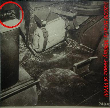
- FORD FACTORY PHOTO -
- Ford GP Assembly Line Photograph -
Factory Installed FORD Fire Extinguisher in Jeep
<click photo to zoom in>
Please don't pirate my pictures or text. Ask
my permission.
Copyright
© 1998-2012 Brian French. All Rights Reserved
Thanks to:
Mike in Iowa, Dan Parmley Jr, and Luther Hanson of the QM Museum for
info on the FSN for WWII Gas & Water cans.
coming soon!
Slave Battery Outlet Receptacle - #A-11792 - located on the outside
of the angular panel on the inside of the right front fender.
"Tool Box, Mechanic's, Army, ""US 1943"" marked, WWII, Rare, VG+, 1@"
Troubleshooting Light, w/ B.O. Hood, WWII Vehicle, NOS RARE, 1@
Valve Spring Compressor, MB/GPW, see photo 1944 TM9-1803A pg.17
"Pick Mattock, NOS ""USA True Temper"" Vehicle Pioneer Kit" Mattocks,
Handled, Pick 5 lbs. #41-M-720
"Pickhead, Vehicle, jeep front bumper, NOS, 1x "1941"
Flag pole holders
license plates
bridge plates
Camo net
Pitcher, Folding, Radiator Water
Canteen Hanger Strap, Vehicle/Mounted, M-1941
Hull Compass Did you know?... the fluid is kerosene. They are found
in 3 colors; Black or Brown Bakelite, and Painted OD. There are also 2
different mold patterns, Early, and Late. There are 3 types of mounts;
Stud, Ball/Clamp, & Pivot. See AAW#2 p212
Hull M4 Jeep Compass Instruction sheet, WWII jeeps etc.
Hull M4 Compass, Black, Early, Pivot, VG++, WWII, needs cleaning,
complete, 1@
Hull M4 Compass, Black, Late, Ball/Clamp, EXC/NOS, complete, 1@
Hull M4 Compass, Black, Late, Stud, NOS in WWII ORD box, 1@
Hull M4 Compass, Brown, Early, Pivot, VG++, WWII, needs cleaning,
complete in box, 1@
Hull M4 Compass, Brown, Late, Ball, missing clamp, VG, WWII, 1@
Hull M4 Compass, Brown, Late, Ball/Clamp, EXC/NOS, complete, 1@
Hull M4 Compass, Brown, Late, Stud, EXC, complete, 1@
Defroster Kit, in metal box, NOS WWII 6v "1942", stores under rear
seat
Paint, SPECIAL GAS DETECTING, orig. "US Chemical Warfare Dept 1942",
for jeep hood star surround.
Rain Trough/Gutter, under hood, #A-100 keeps water off block
Red Light/Siren Switch, Push/Pull w/lock, on-off
Slave Cable Receptacle, NOS WWII, MB/GPW,#A-1792, AAW2,pg191
Spare Tire Foot, X-LG Special DESERT MWO-G503-W9, NOS
T-1 Air Comp. Info, MWO's, Manuals, Blueprints, many Veh. 32pgs
T-1 Air Compressor Engine Mounting Bracket, MB/GPW, Upper, R, 1@
T-1 Air Compressor Hose w/wingnut, NOS WWII, MB/GPW, 1@
T-1 Air Compressor, DESERT MWO-G503-W9, NOS WWII MB/GPW
Tandem Tow Bar Data Plate Alum. , Brass
Tandem Tow Bar Mounting Kit, NOS, mounts Std. bumper & towbar
Tandem Tow Bar Special Reinforcement Pintle-hook Plate, NOS, 2@
Tandem Tow Bar Wood Grill Block, w/ 2 footman loops & 2 straps,
2@
Tandem Tow Bar, ORIG WWII MB/GPW, used, VG+ Willys Part #A-7927
#8-H-1826
"Tow Rope, Manila Hemp, 1"", stores on Frt. Bumper, correct length
w/loops at both ends, 4@"
"Tow Rope, Manila Hemp, 1"", stores on Pass. Fender, NOS, 100ft for"
Water Fording Kit, Late USMC type, most major parts, used 1@
radios
Capstan winch
valve stem protectors
spark plug raincaps
taillight rubber grommets

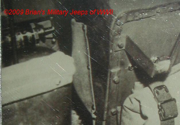
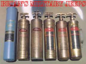
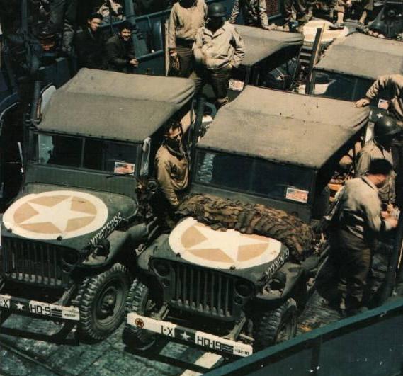
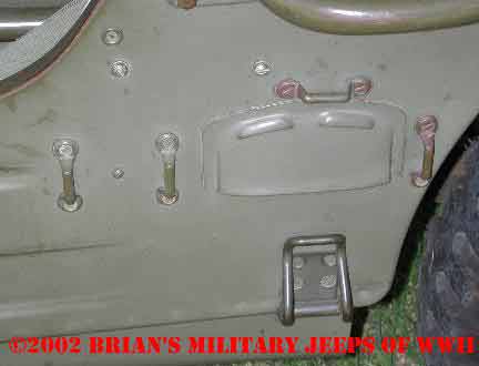
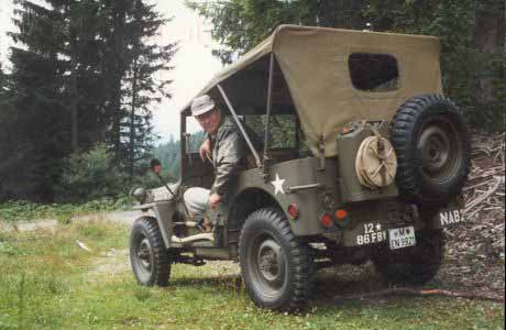
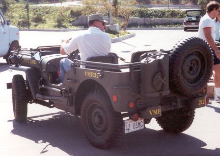
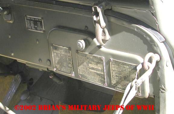
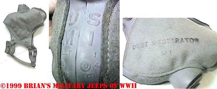
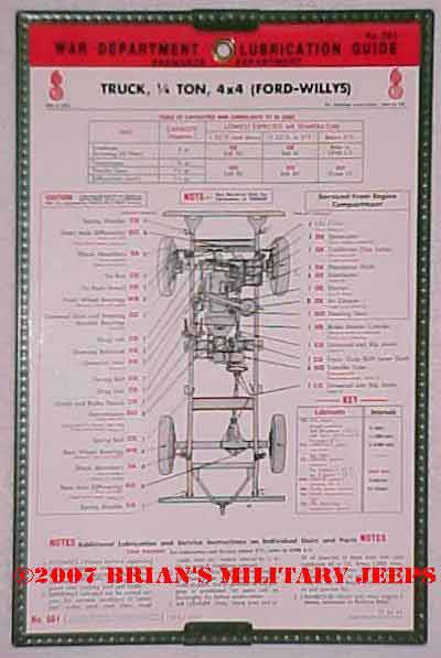
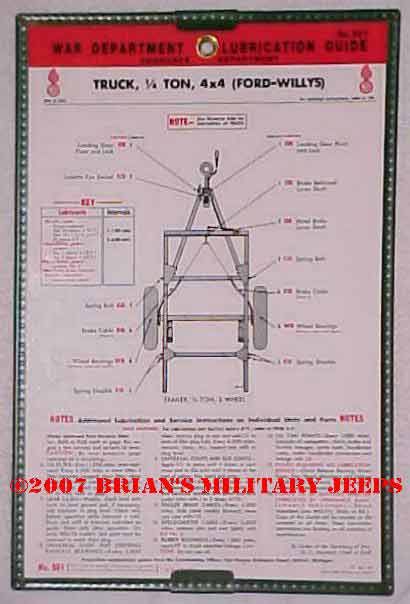
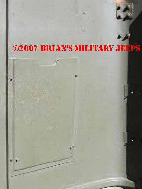
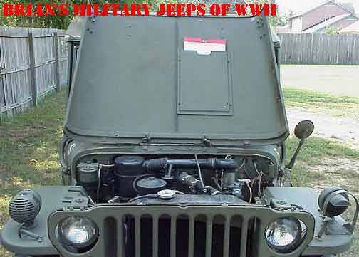
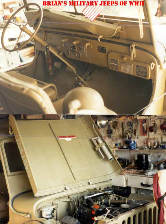
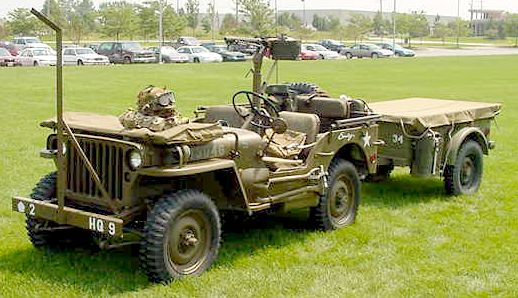
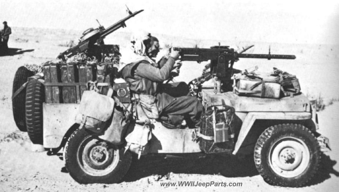
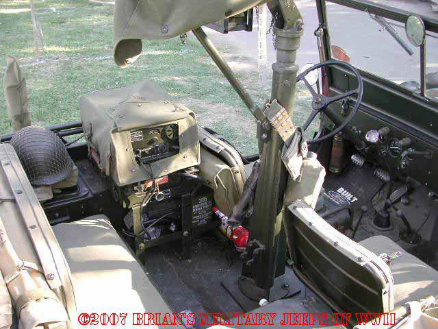
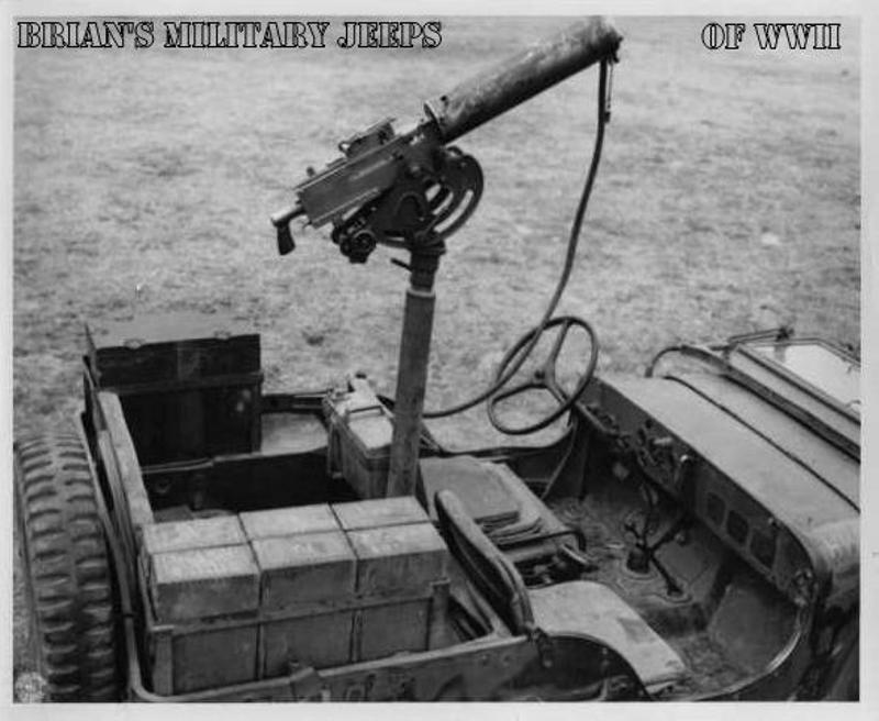
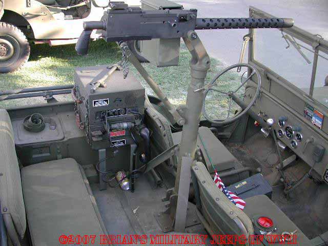
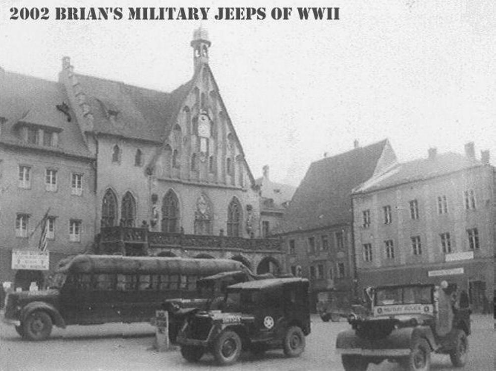
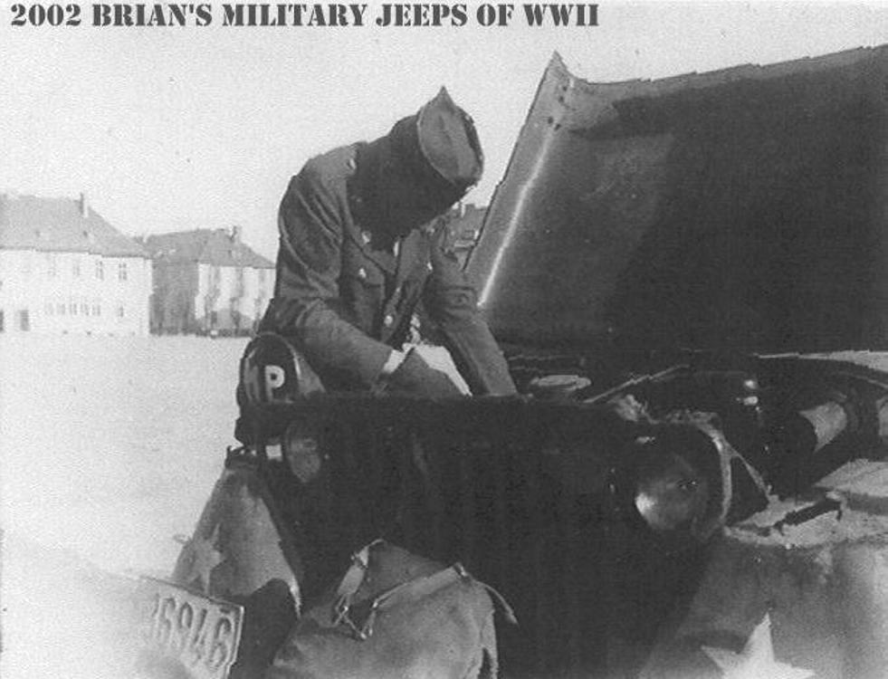
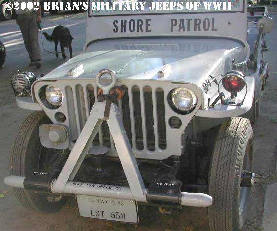
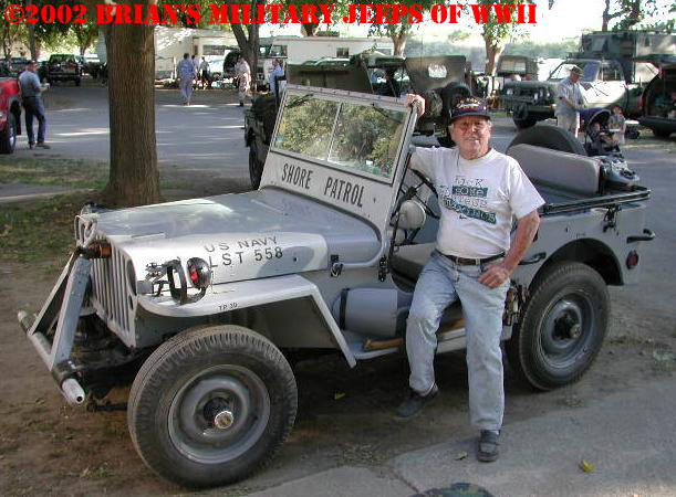
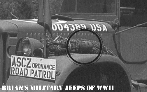
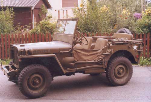
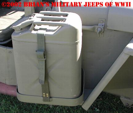